| | | Make your own transmission? |  |
|
+6Mtdmudmower Double W Cross Ranch mowerjunkie03 RichieRichOverdrive Crazy_Carl prancstaman 10 posters | |
| Author | Message |
|---|
prancstaman
Veteran Member

Join date : 2015-02-02
Points : 4888
Posts : 1412
Location : Cleveland,Ohio
|  Subject: Make your own transmission? Subject: Make your own transmission?  August 18th 2018, 11:50 pm August 18th 2018, 11:50 pm | |
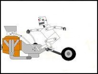
| Hay People, Just brainstorming for right now. I got a few projects in mind and at night (like right now) I got nothing to do but think, LOL. So, throwing the idea around to making my own transmission from other transmissions, like busted transaxles. Transaxles got there weak points, we all know this. From locking them and busting the axles or bull gears, to putting too strong a motor in and busting the input shaft area, to busting the case because they are weak aluminum. Seems like the most common problems. I don't read too much about the gearing going in them or the shafts the gearing is on, but it does happen from what I have read. Maybe missing a shift is why, but this area of the trans seems to be pretty strong generally. The pic below is what I am talking about. It seems that the gearing of the input and the output of these 2 shafts protect them, of a typical aluminum case transaxle.  Here is a pic of a transaxle guts, without the top half of the case that has the input shaft. Note the 2 shafts that I am talking about, with the gearing before and after them. 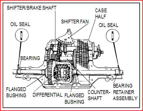 OK, these are the parts I want to get rid of. I used Microsoft paint to erase what I want to use and what is left are the weak areas of the transaxle I want to get rid of. Plus the top half of the case that has the input shaft in it, is not needed for what I have in mind. I think this is a pic of an Peerless 800. Thanks for the link Lauren to the transaxle manuals. 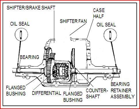 Yah, I know, It's been done, The Peerless 700 trans, or the Foote 3 speed. But no. These trans has the weak links in them like the Peerless 700 input shaft, or are too hard to find like the Foote 3 speed. Having a couple of them would mean you still would be breaking them, and or the shafts are too small to handle the hp like the Foote 3 speed. Would be nice to be able to use any trans for parts, which is what I am proposing among other things too. So my main ideas on this, maybe possible project, would be to use easy to get transaxles that can swap parts on the shafts in question and be way stronger. Keep the gearing on the outside of the trans for the input and output for easy maintenance and to protect the gears with the shafts. 2 gears are easy to keep alive then 6 in a row. The gearing I am talking about that keeps these 2 shafts alive. 1-The input shaft of the case. This input shaft is the shaft everybody puts the small pulley on, on a pulley swap. Even after the pulley swap, the 2 shafts hold together with strength. Typical pulley swaps are usually 1 to 1 from engine to trans, which means the internal gearing is still saving the gears and shafts in question. This internal gearing is 3 to 1. So after the 1 to 1 pulley swap on a transaxle, the internal ratio is still 3 to 1, meaning the input shaft is spinning 3 times for the 1 turn of the countershaft assembly, which is the 1st shaft in question. The countershaft is protected from the 3 to 1 ratio from most damage. 2-Then after the transmission part, there is gearing to the axles. This gearing has a ratio around 6.5 to 1. Could be more or less but not by much. This 6.5 to 1 protects the shifter/brake shaft, which is the second shaft in question and is the output of the transmission part. I never heard of this gearing going bad. This transmission I want to build would have limitations on engine selection and ways to hook up the transmission. I'm thinking a horizontal shaft engine with a centrifugal clutch with a 12 tooth on it and a 36 tooth sprocket for the input of the trans, with an output sprocket of 12 tooth and a live axle sprocket of 78. If I want to run chain. Or a 3 inch belt pulley on engine and a 9 inch pulley on the transmission, with the 12 and 78 tooth sprockets going to a live axle. These 2 examples would be the equivalent of a 1 to 1 pulley swap on a mower with a transaxle. OK, what do you all think of which setup would be stronger and if my transmission would be stronger and easier to fix? There are endless possibilities here not even mentioned or even thought of yet. Would like to here thoughts on that too. | |
| | | | Crazy_Carl
Veteran Member

2018 Build-Off Entrant
2018 Build-Off Entrant
2024 Build-Off Entrant
2024 Build-Off Entrant
Age : 35
Join date : 2017-10-30
Points : 5125
Posts : 2561
Location : Rochester, New York
| | Subject: Re: Make your own transmission? August 21st 2018, 12:37 am | |
| You have a good point about the gearing in these transaxles rarely failing.
So have you ever seen a wheel horse piece transmission? It's the grandfather of the famous 8 speed. The sides are two steel plates that hold the bearings and seals for the shafts. The center housing is cast. Looks kinda homemade. With a lot of machine work something like this could be done with peerless guts.
Have you ever seen RatherBwelding's two speed transmission? Similar concept but his design lacks lubrication and really needs to be contained in an oil filled housing. | |
| | | | RichieRichOverdrive
Moderator


2018 Build-Off Entrant
2018 Build-Off Entrant
2024 Build-Off Entrant
2024 Build-Off Entrant
Age : 21
Join date : 2016-10-29
Points : 6601
Posts : 3628
Location : Lewisburg, KY
| | Subject: Re: Make your own transmission? August 22nd 2018, 12:48 pm | |
| Maybe with a CMM you could trace a peerless case, then with the computer model you could make some changes and mill one out of a block of aluminum in a 5 axis milling machine? That'd be hella cool. You'd be the only person to have a billet case 820, in the world. | |
| | | | prancstaman
Veteran Member
Join date : 2015-02-02
Points : 4888
Posts : 1412
Location : Cleveland,Ohio
| | Subject: Re: Make your own transmission? August 22nd 2018, 11:22 pm | |
| Carl- Yah, never seen one to my knowledge, but that sounds like what I'm talking about. Steel plate case with Ball or roller bearings to hold the shafts. With the input and output on the sides. Could design the case however needed with lots of room on the inside. Just would need to blueprint the shafts and shifter locations which should be easy with a vernier caliper. We shall see on that one, LOL, but would be easier and quicker to do the work with the original blueprint of the transaxle case being used. At the bare minimum I would just need the distance from center to center of the 2 shafts. The shifter arm shaft location will not be that critical and should be able to put it anywhere I choose or just use a cable for simplicity.
Rich- would just need the shafts and shifter locations, probably could get blueprints from the manufacturer by just asking or buying them. And a regular CNC with a 3 axis would do the job with ease with 2 steps, LOL. Scanning the case would be just waving a wond over it once for the blueprints but that has its little corks of not being accurate because production parts that you are scanning always has variations from the blueprints. Just a simple 3 axis Bridgeport would do the job on what you are thinking but would take a while longer to mill out. | |
| | | | prancstaman
Veteran Member
Join date : 2015-02-02
Points : 4888
Posts : 1412
Location : Cleveland,Ohio
| | Subject: Re: Make your own transmission? August 22nd 2018, 11:27 pm | |
| Carl- I seen his 2 speed trans, it works OK for what it is but the shifting part could be better. I would thing this trans would be better in design and would have a built in reverse. | |
| | | | prancstaman
Veteran Member
Join date : 2015-02-02
Points : 4888
Posts : 1412
Location : Cleveland,Ohio
| | Subject: Re: Make your own transmission? November 11th 2018, 9:08 pm | |
| Hay People, Looky what I got. Pulled it out a Toro rear engine riding mower. Think it's a Peerless 500 though. More to come on this subject. 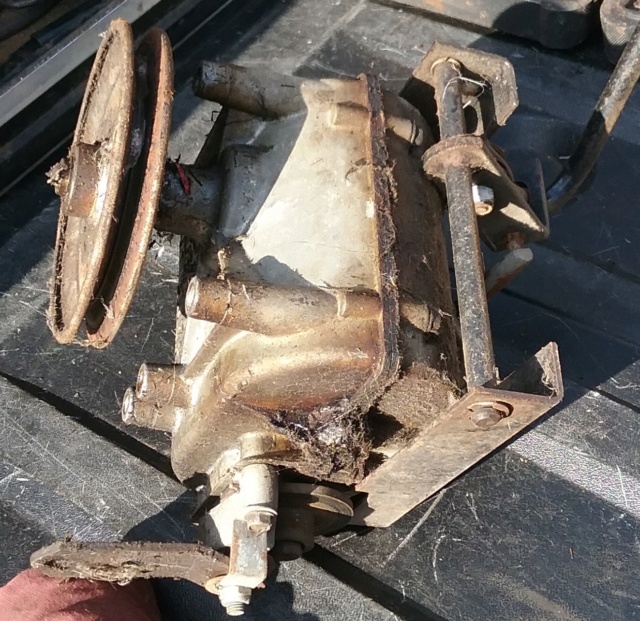 | |
| | | | prancstaman
Veteran Member
Join date : 2015-02-02
Points : 4888
Posts : 1412
Location : Cleveland,Ohio
| | Subject: Peerless 700 Part 1 December 9th 2018, 10:26 pm | |
| Hay People, So, in between projects and working on my truck, I started playing with this gearbox. Took it apart to try to figure out what it is. Got me a Peerless 700 looks like. pic of the tag 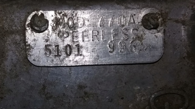 This thing is pretty skimpy. People actually run 20hp through these, WOW. Case is super thin cast aluminum with minimum webbing if you want to call it webbing. But OK. This gearbox could surely benefit from what I will be doing to it. Haven't figured out what I will be putting it in but you can guarantee I will be overbuilding it for whatever I will be running with it, will most likely be my hopped up 22 hp Kohler for my all wheel drive racer, LOL. That build will be another thread, LOL. I'll start this off with just a visual look-over of the case before I pull it apart and get to the nitty gritty of things. Mainly observations on placement of key components. Your eyes can pic up on measurements as different as .003 of an inch. Usually if your eyes can see that it is straight inline then it usually is. Visuals are a big part of reverse engineering something. You can figure out that one part is inline with another part because they have something in common. And makes drawing up blueprints easier. Starting off with a side view. You see the side and the top of the gearbox. See the 2 shafts, the one is the shifter/brake shaft, the other is the countershaft assembly. Looking on the top, you see the bolt holes (4 of them) which was holding the shifter linkage on. 2 of the bolt holes line up with the shifter/brake shaft, while the other 2 bolt holes line up with the countershaft assembly. The webbing on the side for the shafts are on the same lines also. Note the red lines in the second pic. So, the bolt holes are spaced the same as the 2 shafts. 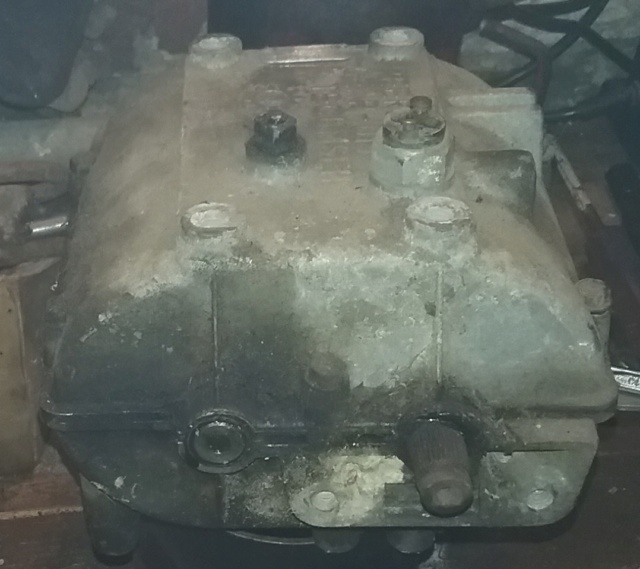  Next, is the other side with the bottom view. The input shaft is inline with the countershaft assembly. Which makes sense, because the gear inside on the input shaft have straight cut teeth so the input shaft's center line would be the same as the countershaft assembly. And a bottom view also. Note the red lines. 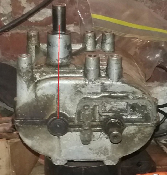 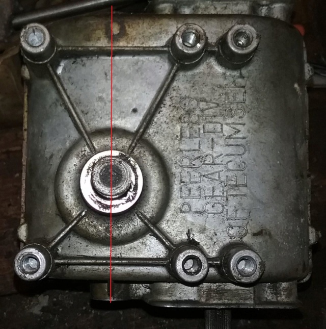 Next, lets focus on the bottom again and same side view and notice the mounting pattern. The mounting holes on the one end line up with the shifter/brake shaft. Note the red lines.  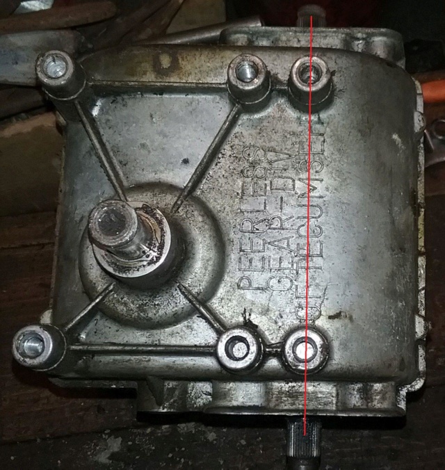 This is only a couple of parts that I noticed real quick. What was noticed, gives me a head start on building a HD version of this gearbox. Just knowing that the mounting pattern starts off right above the shifter/brake shaft, tells me where to put it on a new case, if I wanted to make it a bolt on part. I opened it up long enough to know I needed to stop right here. The proof is in the puddin. 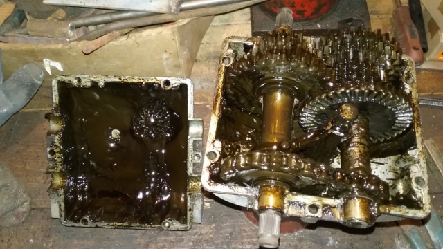 Looks like I got some cleaning to do. Later............. | |
| | | | prancstaman
Veteran Member
Join date : 2015-02-02
Points : 4888
Posts : 1412
Location : Cleveland,Ohio
| | Subject: Cleaned up the Peerless 700 alittle bit December 17th 2018, 12:47 am | |
| Hay People, I cleaned up the gearbox good enough to start measuring it up. The blueprint will be later. This post is more of observations of the parts again, with guesses on how it works as a hole. I been cleaning crap up all day, whether it be in the yard or in this gearbox.  I figured since I was cleaning it up all day and still in the mood to keep cleaning that I might as well do it now. I scraped it out with a screwdriver into my little can of high temp grease for lubing whatever. Nothing serious for reusing it, maybe a tire bead or a rusty shaft on something. 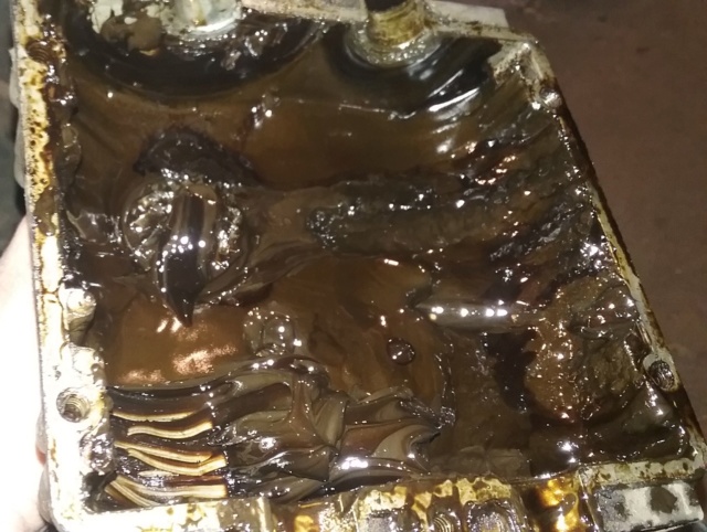 So, this gearbox seems to be divided into sections. This pic is of the bottom half. Note the 2 red lines making 3 sections for the 2 shafts. Reverse gear is on one side which connects the 2 shafts so when engaged the 2 shafts spin the same direction. The middle part of the 2 red lines, on the shifter/brake shaft, is the shifting collar, the shifter arm(which is removes), and shifter keys. While the counter shaft has a spacer and the beveled input gear. And the last section has all the gearing so when selected the shafts spin opposite of each other. This gearing ranges from under drive to overdrive between the 2 shafts. Next is the bottom part of the case which has the input shaft and mounting. All on the bottom half case. Alot of stress happening here on the bottom half of the case. But overall, a pretty simple layout of what you would expect of the inside of a gearbox. A very good design overall.  I took this pic as a reference for how the reverse sprocket sits on the shaft, but I'll focus on the bushing for the post. Measures out to be a regular brass bushing except for the reference notch for the bottom case fitment. The inside diameter is 5/8 of an inch while the outside diameter is 3/4 of an inch. You can just run to the local hardware store and get an off the shelf bushing to replace it, just need to make sure that it doesn't spin in the case after tightening the case. And if it does spin in the case just put a small piece of masking tape on the bushing to tighten it up good enough so it won't. If too tight then file the outside some to get it to work. And check end play on shaft. A good mockup would be needed to make sure fitment will work right. 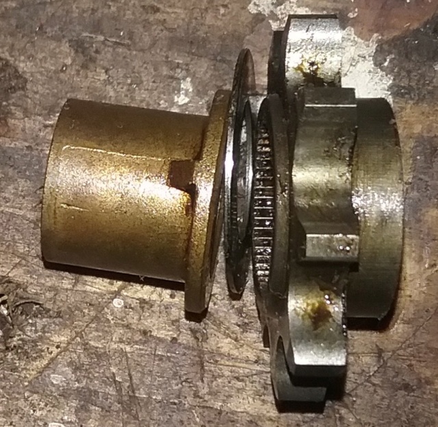 Here are pics of a neat feature of gear shifting. On the shifter/brake shaft, between the gearing are washers, and on the inside of the washer is beveled on one side. To make going into a higher gear easier by compressing the keys on the bevel. Going from high gear to a lower gear I guess you don't need it by the shape of the keys with the key arms. So when shifting up a gear, you can actually get the keys in the gear when not lined up with the gear slot. When the gear slot passes over the key, that is when the key pops into the gear slot. Same thing down shifting too, you just don't need the bevels on the washers to compress the keys on the down shift. The keys take a 1/4 turn or less for lining up with the gear slots on the shaft. So then the key's sides should be flat so when the keys are engaged in the gear slot then the gear slot will hold the key. If the key's sides are angled any, then the gear slots can push the keys down and pop out of gear. This explains why you can easily shift gears while you are moving with this style of gearbox. Even though the shifter is in the gear selected, you are in neutral until the keys pop into the gear slots. Until the keys pop into the gear slots they are compressed and waiting for the gears to line up, when going into a gear selected.    Next, I popped the clip and pulled the input shaft out. The seal for this shaft is a regular O-ring. Still need to pull the roller bearings out of the case. I guess a hammer and a socket would work, wait a minute, I got something better, LOL.  I just happen to have a hydraulic press layin around, LOL. Worked great!! A small socket on top and a large socket underneath it to hold and catch the 2 roller bearings. 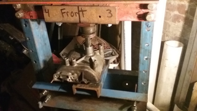 OK, here are all the parts for the input shaft in order of removal. At this point the gearbox is completely apart. 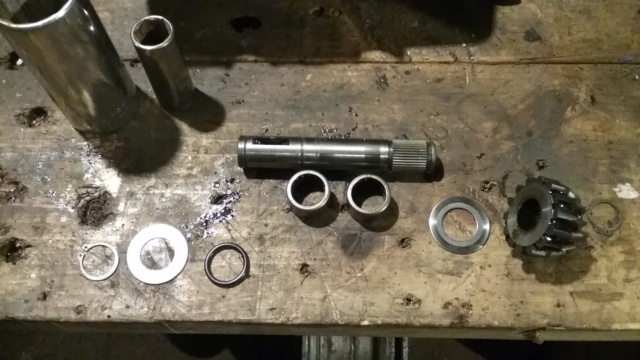 Everything is apart and bagged up in order. I still got alot of cleaning to do but clean enough to start measuring things.  It's late so that's it. Maybe you all would like to leave a comment on how your Peerless 700 failed. Input would be good. Later...... | |
| | | | prancstaman
Veteran Member
Join date : 2015-02-02
Points : 4888
Posts : 1412
Location : Cleveland,Ohio
| | Subject: Little update on progress December 26th 2018, 11:41 pm | |
| Hay People,
Been measuring up the Peerless trans for blueprinting. Taking pics on how I got the measurements too, to show how I did it. Going to take some time on this. Plus I need to make a jig at work to put in a hole to measure it up right for accuracy. In the end, there should be a downloadable file (I hope) of the blueprints necessary to mill your own housings with how to's to modding it in a way never thought of. I plan on using mine in a very torturous way so upgrading is going to be necessary and a stock housing and parts won't hold up, if I use this gearbox. I'll be making the decision later if I'll be using this one or just making my own from scratch with what I learn here.
I did do a quick search on blueprints for a Peerless 700. No joy. Only exploded views of parts. Everybody just wants to sell them which means everybody is keeping the blueprints a secret. I guess I'll be pissing off some manufacturers with this one, LOL. Around $200 will buy you one or another one after you break the first one, LOL. Supply and demand I guess. In the search I found one of the pics from this thread, which I thought was funny.
Anyways. Measuring this gearbox up seems to be easy with numbers that seem expected. Like shaft centers, diameters, and so on. I need to put it together and pull it apart like a million times to get the right numbers. Just alot of speculations right now with vague descriptions, LOL.
So, later People. I got work to do. | |
| | | | mowerjunkie03
Member


Age : 20
Join date : 2018-10-29
Points : 2388
Posts : 342
Location : Burnt Ranch, California
| | Subject: Re: Make your own transmission? December 27th 2018, 11:42 pm | |
| Cool idea man! I have been hoping someone would try this. If it works out for you I want to try it on a transaxle maybe a spicer since the guts are okay the cases just aren't great. | |
| | | | prancstaman
Veteran Member
Join date : 2015-02-02
Points : 4888
Posts : 1412
Location : Cleveland,Ohio
| | Subject: Re: Make your own transmission? December 28th 2018, 7:15 pm | |
| - mowerjunkie03 wrote:
- Cool idea man! I have been hoping someone would try this. If it works out for you I want to try it on a transaxle maybe a spicer since the guts are okay the cases just aren't great.
You got the right idea. I plan on doing it and showing how to do it so other people can do it on there own with what they have. A Spicer transaxle was one of the gearboxes in mind. Maybe even simplify the idea so you would be able to use a good ruler to make the gearbox. There usually is some room for error on the measurements. Meaning the gears have room to be spaced in a range that is loose or tight and still work good enough. I will be explaining everything in detail. And this is just on the Peerless 700 series. I got a couple other transaxles I'll be doing this to also, using the same methods as I am here. Just will take a little time, is all. | |
| | | | prancstaman
Veteran Member
Join date : 2015-02-02
Points : 4888
Posts : 1412
Location : Cleveland,Ohio
| | Subject: Starting on the first Transmission - Peerless 700 Blueprints part 1 December 31st 2018, 9:26 pm | |
| Hay People, Trying to get this going. Figured I start off with how I will be measuring the whole gearbox up. I tried looking for a blueprint of some sorts online but found nothing. Googling did nothing but cause frustration for a half hour. So I decided to make my own and share. I'll be focusing on how I do it in this post. This creates certain problems doing it myself with a production unit. The gearbox was built on a production line which creates problems all it's own. From machines loosing accuracy by just being used, to the worker recovering from a hangover from that bachelor party the night before, and the QC department understanding the term "Good Enough". And that's before it leaves the factory. Then being how old? And it being a used but working unit with ware on it. All in all, nothing I haven't done before. Experience counts. This is where an educated guess counts. No eyeballing for the most part. To draw the blueprints, I'll be using a CAD program for the experience of using it. No hand drawn pictures. An upgrade to myself that doesn't involve putting a hole in me to do. Pretty safe, LOL. I'll be explaining how I come up with the measurements because they are not straight forward to do for the most part. It involves measuring and using a math equation to get the finale measurement. So my pics I took shows the caliper of a measurement but is not the finale measurement on most of the pics. Got to apply the right equation to the measurement. The pics will be used mainly as a first step of a process. I'm starting with the case of the gearbox. I'll be measuring from hole to hole alot and need to know the centers of the holes and then to another hole's center. Then measuring from the center of the case to an area on the sides or bottom walls of the case too. Identifying machined surfaces to know where to start the measuring. And techniques on how to make a point to start measuring from. #1 Measuring form a center of a hole to a center of a hole. I made a pic to help explain this (below). You don't actually start from the center of the hole. First- measure both holes diameter and divide by 2 to find half of the diameter. Then measure from the edge of the first hole to the edge of the second hole. Now add the 2 half holes and the measurement between the holes. This makes the finale true measurement from the center of the first hole to the center of the second hole. Measuring a hole or circle and dividing by half is mathematically how you draw an imaginary line through the center of the hole or circle. This is shown in the pic as the red and orange lines. You're using the caliper to measure A which is between the holes. Then adding the 2 halves to A. When measuring a series of holes in a straight line, you always use the first hole in the series to start with to measure the others. Never start with the second or third hole to get the measurement of the next hole, you loose accuracy doing it this way. In the pic, you measure from hole 1 to hole 3 (example B). Never from hole 1 to hole 2, then from hole 2 to hole 3, never that way, is not accurate and will be off by thousandths of an inch.  #2 Measuring from a straight edge to a machined surface. Measuring from the center of a case from in the air to a surface is impossible to do. To do it right you need to find a point to start with. The milled surface of the case which is usually the outer edge of the case if you are lucky. The idea is to extend this surface over the place you want to measure to. Do this with a straight edge, then measure from the top of the straight edge to the place to be measured going straight to it (never on an angle). Then subtract the thickness of the straight edge. Not the best way but does work pretty well. The pic below is the example of this. Just don't forget to subtract the thickness of the straight edge. So the formula is= the measurement minus the thickness of the straight edge= The straight edge is 1 inch thick and the measurement is 4 inches, then 4-1=3 inches to object from milled surface. 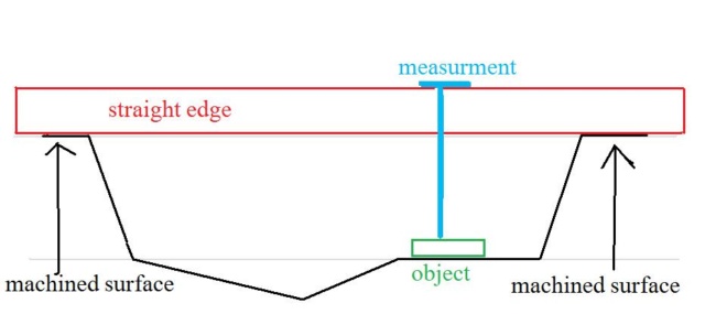 #3 Finding a hole or object location inside an object. To do this, you need 2 walls that have a machined surface as a starting point and the end result is in grid form with 2 lines that connect for the center of the object being located. Pic below shows this with the green lines coming from the walls going straight to the object from the 2 walls. Doesn't matter if the walls are not at 90 degrees just as long as you go straight in from the walls it will work. Using a corner and finding a certain angle then going in a certain distance is to hard to do and is not too practical to do in a production of parts but is used. Which is why it is in red. I will be using the green lined method. 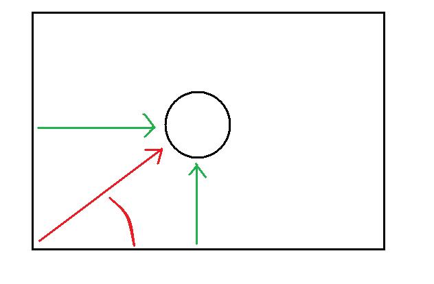 I think that is it for how I will be doing this. There are other things that will be done to be able to use the above methods. These things involve making jigs to extend a surface to get a measurement. Like from a threaded bolt hole to a threaded bolt hole, you can put bolts in the threaded bolt holes and measure from the shank of the bolt. When you screw in a bolt, it wiggles in the threads, to straighten up the bolt you use a nut on the threads and tighten the nut onto the case and when you tighten the nut it will straighten up the bolt and not move, with the shank exposed. I'll be making jigs to fit inside holes to extend the heights to be able to measure them for locations. Mill the jig in a lathe for roundness and to fit in the hole snugly. I got to make the jigs on a lathe at work, then finish up the blueprints of the case before I go further. Till then, Later. | |
| | | | prancstaman
Veteran Member
Join date : 2015-02-02
Points : 4888
Posts : 1412
Location : Cleveland,Ohio
| | Subject: Little update on progress January 24th 2019, 1:44 am | |
| Hay People, Been slavin away at this. Almost done with the drawing part of the gearbox and need to put in the measurements on the pictures of the parts and a couple of parts to still draw up too. Figure I would give an update to help keep interest alive. CAD has been going pretty easy but involves alot of math to make the pics accurate and in proportion since I want the pics to be accurate too. Nothing is freehand drawn. If the part has a slot in the blueprint, that slot will be the same size as the actual part, sort of thing. Here are a couple pics I snipped from the blueprint. The vertical input shaft. One pic is of the shaft itself and the other pic is of the shaft, the housing part of the case, roller bearings, and washers as they are on the actual gearbox. Each part has it's own color and is in proportion with the other parts. Even the endplay of this shaft is accurate, LOL.  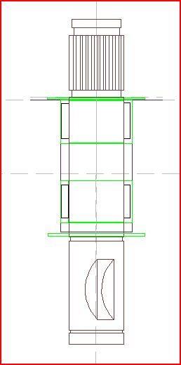 It's late, Later. | |
| | | | prancstaman
Veteran Member
Join date : 2015-02-02
Points : 4888
Posts : 1412
Location : Cleveland,Ohio
| | Subject: Peerless 700 Blueprints part 2 January 30th 2019, 10:56 pm | |
| Hay People, Figure I get this ball rollin, for the blueprints of this gearbox. I took over 100 pics for info of the gearbox so I wouldn't have to remeasure the parts. I won't be posting all the pics but will be showing what I think are the important one's. If someone would like a pic of a specific measurement then I will post it. Keep in mind that the measurements are of a used unit, meaning that the parts will be showing wear on them. Me drawing up these blueprints are of my gearbox only and are not from the original blueprint of this unit. With this said, a comparison of my blueprint to the original would be thousands of an inch off because of ware on the parts, the machines that made the parts will have variations from part to part in production, the assembler in the factory having a rough night before and not at 100% that day, and who knows what else. But My blueprints could be used to remake the parts to fit in the original spot. Since the parts are not perfect, this shows that there is forgiveness in imperfections. I will not be drawing up every part either, like the gears themselves. To hard to draw and I dought anybody will be making a set of gears let alone be able to. My purpose in doing this is to make from scratch a case, make or modify main shafts, and modify original main parts. My blueprints will be reflecting this. But if someone requests a measurement of a part, I will do my best to do so. I'll start with a small simple part, the bushings. I'll show the blueprint of the part, then the pics of the measurements , as proof and to show how I did it. I didn't bother to put the little tab in the blueprint because if you are making it or buying one off the shelf, would most likely fit snug in the case and not spin anyways. 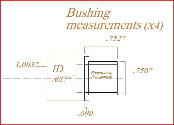 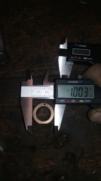 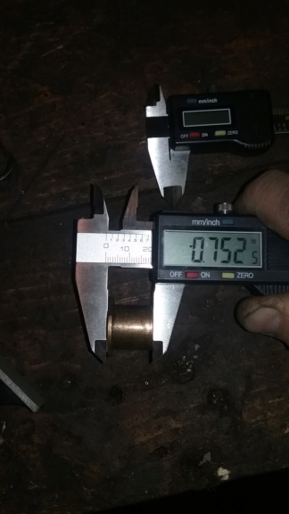 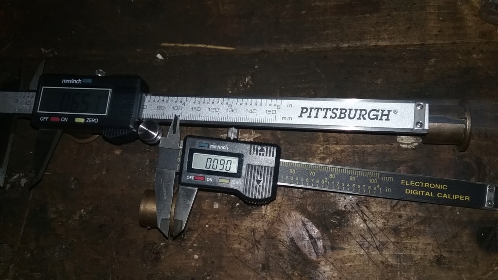 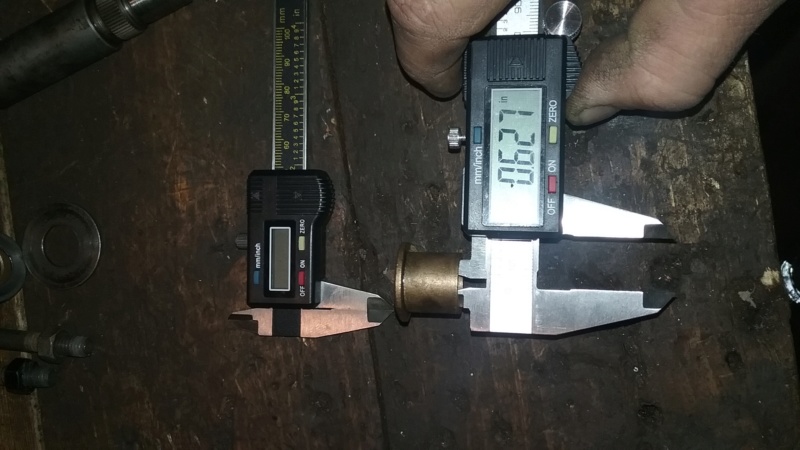 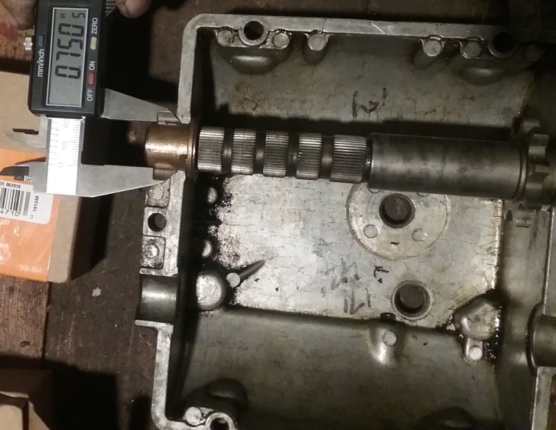 The bushings are pretty straight forward in measuring them. Would be easy to make on a lathe of just buy one at a hardware store. As I mentioned before, this one shows ware as I am guessing. I would think a new bushing would measure up on the inside diameter as .625". If the shaft this was on had an endplay on it that you thought was too much, you could make one with a lip on it a little more then .090" to take some slop out. If you are making a bushing, the most critical measurement would be the outside diameter, because if too small then it would spin in the case or if too big then when you tighten the case you would bend or break the case trying to squeeze on the bushing. That would be the .750" measurement which is probably why it is this measurement on my part, and is the measurement to be expected and not .074" or ,076". That's it for now. Been a long day for me and it's bedtime. Later.
Last edited by prancstaman on February 6th 2019, 6:45 pm; edited 1 time in total | |
| | | | prancstaman
Veteran Member
Join date : 2015-02-02
Points : 4888
Posts : 1412
Location : Cleveland,Ohio
| | Subject: Peerless 700 Blueprint part 3 January 31st 2019, 9:28 pm | |
| Hay People, Here are some more simple parts I finished. The washers/ spacers on the ends of the shafts and the roller bearings on the vertical input shaft. These washers take up end play of the shafts, so a more appropriate name would be shims but I'm calling them washers because that is what they look like. Yup, I plan on torturing you fanatics with WRONG names, LOL. This pic of the blueprint show where the washers are in the gearbox or how they sit in the gearbox from a certain point of view with a reference spot too. The washers for the 2 main shafts which control the end plays of the 2 shafts (shifter/brake shaft assembly and counter shaft assembly). 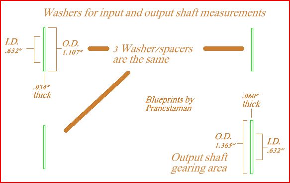 Pics of the measurements of the washers for the shifter/brake shaft assembly and countershaft assembly. 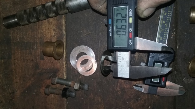 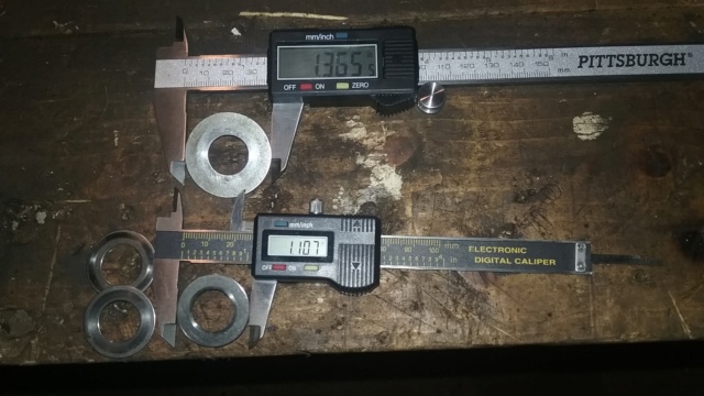 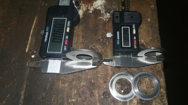 This pic of the blueprint below is of the vertical input shaft section with the washers and roller bearings in their respective places as it is with the gearbox mounted in a frame. The pulley would be on the bottom and gear inside of the case would be on top. I'll be providing the placement specs of the roller bearings later, this post is only about the measurements of the parts. A special note about the measurement of the roller bearings= the blueprint shows an outside diameter of .814" which is a measurement of the roller bearings not being in the case. Since the case bore that houses the roller bearings measure smaller, the roller bearings are pressed into the case. The press fit between the 2 parts is between .002" to .003". Also, there is a limit on how many times you press the roller bearings into and out of the case to where you stretch the case bore enough to where the roller bearings will drop in instead of being pressed in, this is bad. Only pull out the roller bearings when you need to. Too many times removing them and putting them back in will result in scrapping the case because the roller bearings keep moving up or down while driving. From experience, I figure you have 4 times (more or less) to remove the bearings and putting them back in safely before the case bore is stretched so much that it won't hold the roller bearings anymore, then the case half is scrap. A little red locktight or thread locker on the outside of the roller bearing race should help hold them when pressing them back in at this point for one or two more times. 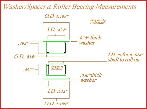 Pics of the measurements of the washers and roller bearings for the vertical input shaft. 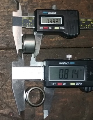 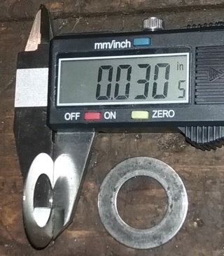 OK, all the washers have the same inside diameter size. This is where the thickness and outside diameters matter. On the shifter/brake shaft assembly, uses a .034" thick washer on the reverse sprocket side, and a .060" thick washer on the gear side because the washer also holds the gears on and has a bigger outside diameter to do this. The countershaft assembly uses two .034" thick washers. The vertical input shaft uses two .030" washers, one washer on the inside of the case and one washer on the outside of the case which also holds the O-ring seal for the shaft in place. That's it for now. I'll do a couple more parts and post them when I get done. Later.
Last edited by prancstaman on February 6th 2019, 6:53 pm; edited 1 time in total | |
| | | | prancstaman
Veteran Member
Join date : 2015-02-02
Points : 4888
Posts : 1412
Location : Cleveland,Ohio
| | Subject: Peerless 700 Blueprint part 4 February 4th 2019, 9:41 pm | |
| Hay People, Finished another part, the vertical input shaft. This is the shaft you put the pulley on, on the bottom. The blueprint shows how it sits while in the gearbox. I will post only a couple pics of the measurements, what I think are the important ones. For this part alone I took around 18 pics of the measurements. The gear on this shaft inside of the gearbox, I just took a measurement pic of the length of the gear. If someone is switching gears then they would be matching the gear with the corresponding gear on the countershaft also and a blueprint of the gear would not matter. The vertical input shaft blueprint. 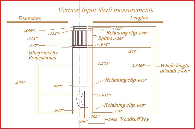 Pics of the measurements. The shaft size is pretty much 5/8 of an inch. The interesting part is that the shaft chokes down to almost 1/2 of an inch, of a measurement of .570" where the gear fits on inside of the case. I would consider this the weakest part of the shaft. 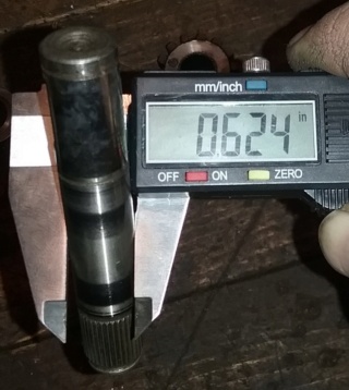 Total length of the shaft.  Length of the section that holds the gear on inside of the case. 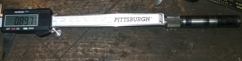 The gear that fits on the shaft, and the length measurement of .763". 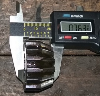 Lets brainstorm for a minute on this part. It would be a stronger part if the spline section wasn't so small. Maybe keeping the same size of the shaft all the way to the end there. But that would need a bigger gear on this shaft with a corresponding gear on the counter shaft to match because the original gear for this gearbox is not thick enough to cut the center spline out to a bigger diameter and then cut a key way in it. You would need to know your parts to do this mod in order to fit in this gearbox. This was one of a couple of reasons why I wanted to eliminate this part from the gearbox and change the input of power from a vertical input to a horizontal input using the counter shaft as the input shaft also. That's it for now. later. | |
| | | | prancstaman
Veteran Member
Join date : 2015-02-02
Points : 4888
Posts : 1412
Location : Cleveland,Ohio
| | Subject: Re: Make your own transmission? February 6th 2019, 9:26 pm | |
| Hay People, Got a few more things done. This post will be on the horizontal input shaft (counter shaft). This shaft alone, I took over 30 pics for reference. Again, only a few select pics will be posted. Blueprint of the counter shaft as a whole, then a closeup of the shaft. There was too many measurements to squeeze them all in at the same font so the spaces inbetween the main sections I shrunk the font, the closeup pic will show the smaller font better. I been setting up the drawings when writing in the measurement to where all of the lengths are on one side of the part and all of the diameters are on the other side of the part. Unless otherwise said, I will keep doing it this way.  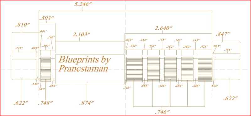 Pics I chose to post. The counter shaft is placed in the top case and has the washers and the bushings on. Then took a measurement of this in the case to show how long the assembly is. Note the case where the bushings sit, has machined surfaces for the lips of the bushings to push up against. This measurement of the case going across is 5.537" (I'll post that pic later) between these machined surfaces. With the shaft assembly measured at 5.496", you can subtract the shaft assembly measurement from the case measurement to find an end play of .041". This measurement does not mean there is alot of endplay on the shaft, it means there is .041" of adjustment on the shaft to set teeth bite on the vertical input gear to the counter shaft gear. Knowing this helps setting up the gearing to have proper mesh for longevity and strength between the gears. To check the teeth bite between gears, you can paint both gears teeth and do a mock up with everything on both the vertical and horizontal shafts. Then with tension on the counter shaft you turn the vertical shaft in the correct rotation. The tension on the counter shaft gear will wear the paint off of the gears on where the two shaft gears teeth make contact with each other. Disassemble and read the paint on both gears to see how they make contact with each other. You would use the washers on both of these shafts to adjust the contact between these two gears for proper mesh. Now to the point of this pic. The shafts adjustment for proper mesh is only half of it. The forces on this counter shaft from the vertical input shaft force the counter shaft to the side of where the reverse sprocket and chain are. For racing on deleting reverse, the strongest way would be to remove the chain and keep the sprocket in place on this shaft, since the sprocket fits on the shaft the best as compared to a spacer that fits over the spline part and leaves a gap. The original reverse sprocket would handle the thrust loads the best against the washer on that side.  Shaft diameter for the bushings. 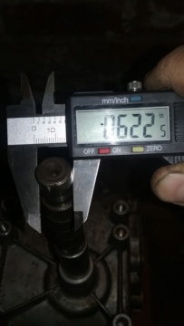 The spacing between the gearing and sprocket.  The section where the gearing goes. 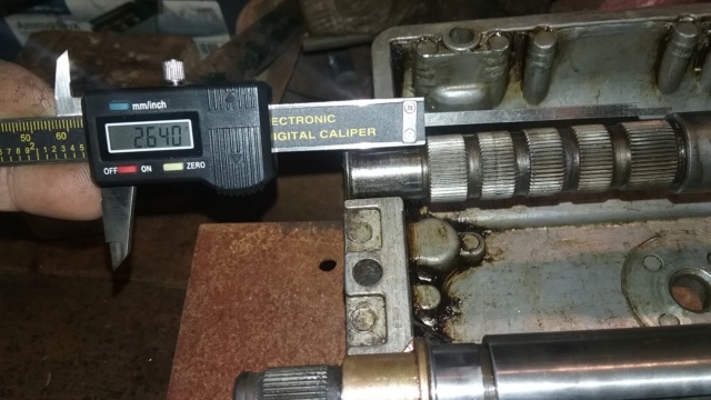 The reverse gear sprocket length.  That's it for now. Later. | |
| | | | prancstaman
Veteran Member
Join date : 2015-02-02
Points : 4888
Posts : 1412
Location : Cleveland,Ohio
| | Subject: Peerless 700 Blueprint part 6 February 7th 2019, 11:13 pm | |
| Hay People, Time for the next part that I finished up. It's the shifter/brake shaft. I'll post 3 pics of the blueprint. First pic of blueprint will be of the whole shaft, has the small fonts of measurements on this one too, so 2 closeups pics also. Blueprint of the shifter/brake shaft. 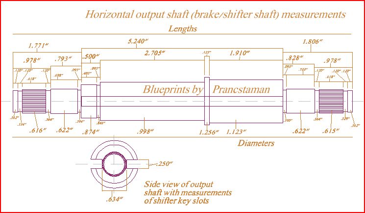 Closeups of the shaft.  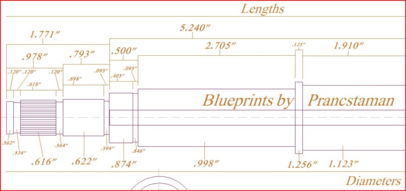 Now the pics of the shaft.  Note how wide it is with the bushings and washers on it. Case width is 5.537" and this shaft as it is assembled is 5.515", which has an end play of .022". Half of the other shaft. This shaft has only torsional loads on it to worry about. 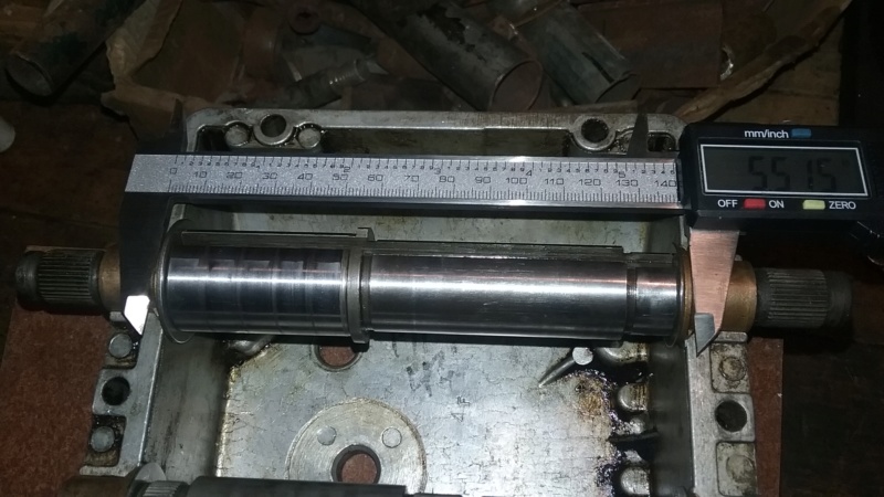 Next couple of pics are of the weak links of the shaft. Max whole diameter of the shifter/brake shaft (meaning the solid part of the shaft) maxes out at .634", just over 5/8" on this shaft. Ofcourse the shaft, in area's measure well over an inch but is not solid. The solid part of the shaft that runs all the way through the shaft is .634". So basically the shaft is just a bit stronger then a hardened steel 5/8" jackshaft.  Next 2 pics are of the smallest parts of the shaft. Measuring just over 1/2 inch. The places are just before the splines where the output sprocket and the brake disk go. Both sides of the shafts are about the same and measure up at .564" and .567". These spots would break first on this part.  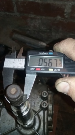 OK, lets brainstorm. This shaft, at it's strongest part is just over a half inch thick. Meaning the strongest part is it's weakest part. Hope the shift keys break first,LOL. I think it would be reasonable to expect the strongest part of this shaft to be where the shift keys are on the main part of the shaft where the gearing is. This would involve remaking the shaft and having the splines not be there. Instead of the splines have the ends be 5/8 inch ends with woodruff keys on them, maybe. If I redesign this shaft to make it myself, I would make it so the side of the shaft with the gears on it, would be the output part of the shaft only with a 1 inch shaft sticking out for the sprocket and the brake be on the other end only. The part where it measures 1 1/4 inch that hold the gears in place in the center of the shaft can be a removable snap ring or 2 snap rings for the thickness of it, or better yet, a press on ring to hold the center of the shaft together. That would be killer, well maybe just a rock crusher atleast. I think I got the perfect shaft I can widdle this out of, it's a hunk of steel from a car axle (Ford 8.8 axle shaft) that I can use. Definitely going to be a rock crusher, if anything, LOL. more on this part later. For now, it's just learning and doing the math.  Later.
Last edited by prancstaman on March 15th 2019, 9:14 pm; edited 2 times in total | |
| | | | prancstaman
Veteran Member
Join date : 2015-02-02
Points : 4888
Posts : 1412
Location : Cleveland,Ohio
| | Subject: Peerless 700 Blueprint part 7 February 20th 2019, 11:36 pm | |
| Hay People, Got a little more done. This post will be on the shift collar and the shift keys. I won't be drawing up the shift keys because I don't think anybody will be trying to make them since they are spring steel. I will be showing pics of the shift keys to show how a (well for the most part) good shift key will look like. Here is the blueprint of the shift collar. 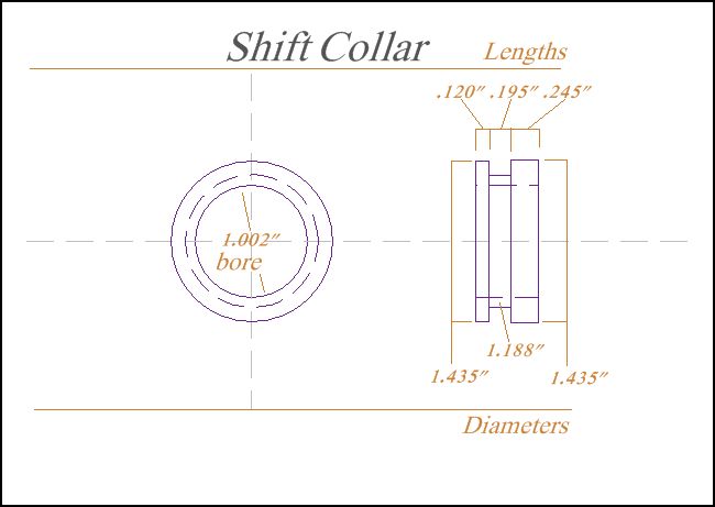 This pic shows how the parts fit together in the correct orientation. Note that the shift collar has a thick side and thin side. The thick side goes towards the gears. If the collar is on backwards then this will throw off the spacing within the shifting of the gearbox and problems of the gearbox will be not going into gear when a gear is selected, or the prongs not fully engaged into the selected gear and might pop out of gear, or shifter is in between gears on selector and gearbox is in a gear. 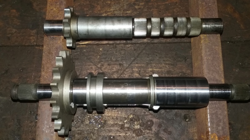 Pics of the measurements for the shift collar. 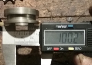 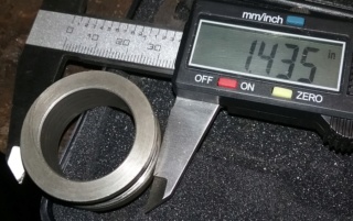 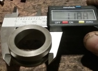 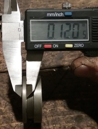 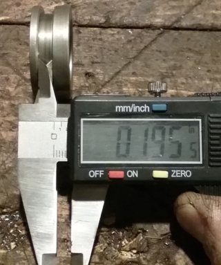 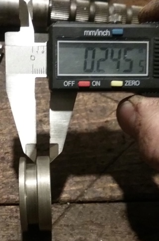 This pic shows the length of the shift key. 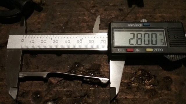 This pic shows how high the shift key prong rises when it is in the groove of the shaft. Any higher and the prongs won't go into the gears because it will be above the gear slots. Any lower and the prongs won't stay into a gear. The height is 3/16 of an inch. 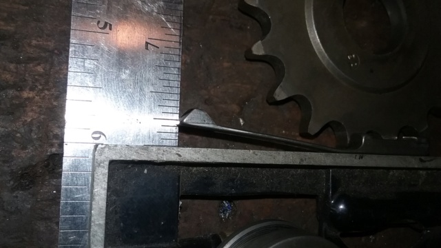 The reverse sprocket has large slots for the shifter keys to engage into. With such large slots, there will be play in the drive system where the keys move around inside the large slots, which in turn is back and forth movement in the driveline. What this means, you will coast while in reverse until the keys are up against the sprockets slot stops. I show the width of the reverse sprocket in case someone wants to make a spacer in place of the reverse sprocket. Making a spacer, the result will be that the shift keys won't engage into the reverse gear at all. 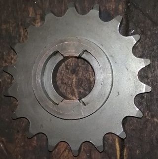 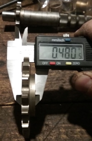 That's it for now. I still have to finish the shifter fork blueprint. After that, then onto the case. Later. | |
| | | | prancstaman
Veteran Member
Join date : 2015-02-02
Points : 4888
Posts : 1412
Location : Cleveland,Ohio
| | Subject: Peerless 700 blueprint part 8 March 9th 2019, 2:15 am | |
| Hay People, Little update before I start. Got the case halves blueprinted ready for posting. I figured out the CAD program to draw up the shifter fork, just have to do it now. This post will be on the bottom mounting boltholes mainly. Then the next post on the vertical input bore since that is a part of this. Since this thread is about making your own transmission, I left the case outline off the blueprint because the case is one of the weak parts, but all the boltholes and bores will be in the blueprint. Need to know where to drill the holes in the new case in other words. Here is the blueprint of the mounting boltholes in the bottom half of the case. There is other stuff too but this post will be on the bolthole pattern and the pics will support this.  The pic of what is draw in the blueprint, for perspective. This pic was posted before for the mounting bolt pattern to start over the output shaft. This is where I put the 2 boltholes over and gave me a starting point for the pattern. I couldn't tell ya if this is actually how it is in the original blueprint but on my blueprint that is where it is. Mathematically, it makes sence for this. I must have crunched the numbers a thousand times and this seems to be the best and easiest outcome. 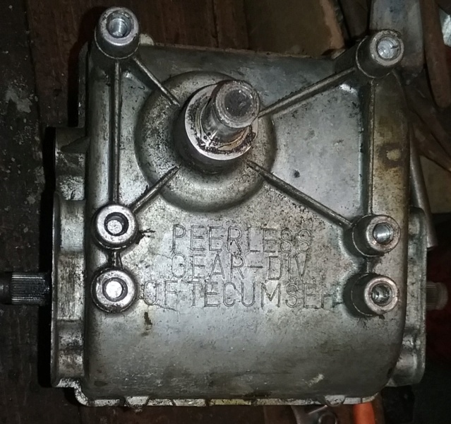 OK, how I figured out the bolt pattern was done through an equation. The caliper only shows part of the story by measuring between the boltholes and the equation tells you the exact distance from the bolthole center to bolthole center. Pic below. Caliper says .691". Need diameters of bolts- .311" and .309". Then need to half up the bolts with math to get to the center of the bolt. So half of one bolt is .1555", half of the other bolt is .1545". The equation in a sentence is ( bolt half + caliper reading + bolt half). Now the equation in math is (.1555" + .691" + .1545") = 1.001" So the distance from the bolthole over the output shaft to the next bolt, from center of the bolt to the center of the next bolt is 1.001 inches. That's alot of thinking there but that is how it's done. Been doing this for the past 2 months. The other side is the same distance which is the start of the bolt pattern from back to front. 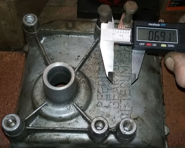 The next bolthole needs measured. Need to start from the first bolthole and skip the second bolthole to measure to the third bolthole. Never measure one after the other, always measure from the start to the next in line. Measuring one to the next and keep doing this creates errors and adds false length to the finish outcome from defects of the parts. Doing it correctly, in a series of parts in a line, it will go like this by measuring, 1 to 2, 1 to 3, 1 to 4, and 1 to 5. The wrong way to measure the same line of parts, 1 to 2, 2 to 3, 3 to 4, 4 to 5, would add false length to the pattern. With this said, below I measure from the bolthole over the output shaft (starting point) to the 3rd bolthole in the pattern. Measures up as 3.691 on the caliper. Add to this 2 bolt halves to find the center of the bolts which is the center of the boltholes. The equation is .1555" + 3.691" + .1545" = 4.001". The other side is the same.  Next is how wide the bolt pattern is. Caliper says 4.002". Equation is, .1555 + 4.002 + .1545" = 4.312" between each set of boltholes.  That's how I got the mounting bolt pattern. Now to place it on the case. This next pic shows the mounting pattern is not centered on the bottom case half, but off to the side. Note the red line, shows that the bottom mounting bolt pattern does not line up in any way with the top mounting bolt pattern. The blueprints will show this, eventually. 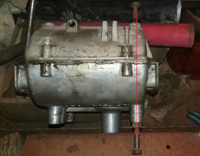 Next pic will place the bolt pattern onto the case. There is alot going on here so bare with me. To place the bolt pattern onto the case, I needed a starting point. That starting point needed to be a milled surface. That milled surface was inside the case. Yup, that sucked big time, LOL. I used the bushing stops on the output shaft inside the case. I picked this starting point because the main shafts of the gearbox is pretty much the main focal point of all the parts of the gearbox and determines where everything is placed. What holds the main shafts in place are the bushing stops and bores. The bushing stops does just that, keeps the bushings from popping out of the case by the lip of the bushing pushing on the case. And also has that notch that keeps the bushing from spinning in the case too. So the bushing stops are a thought out milled surface on each side for controlling end play of the shafts. Would be the same on any case half made, theoretically. So, in this pic you see the case half held in place by a clamp to the flat plate steel so it don't move. Then there is a carpenters square with the straight edge against the case. And a caliper reading of .860". If you followed with what I said about the bushing stop inside the case being the starting point, then the path of me measuring would be in a shape of a "J". Oh boy! Which would be, put into words... Measuring from the bushing stop to the outside edge, then bring that edge straight up with the carpenter square, then over to the bolt with the caliper for a measurement, and finally half of the bolt for the center of the bolthole. Took me a couple, well, quit a few tries to get this right. Now for the equation, LOL. Yup, need to come up with a number and needs to be spot on too, to place the mounting bolt pattern onto the case. I figured it by going backwards. The equation is, half of the bolt + caliper reading - from the bushing stop to the outside edge of case. The carpenter square just ensures the outside edge is the same edge from top to bottom and is not part of a measurement. Now in math, .1555" + .860" - .640" = .375" from the bushing stop that is inside the case over to the bottom left bolthole center of the mounting bolt pattern in the pic. This places the mounting bolt pattern onto the case side to side.  I measure the other side to verify the measurement. The equation is the same, half of bolt + caliper reading - from the bushing stop to the outside edge of case. Now in math, .1545" + 1.335" - .640" = .850" from bushing stop that is inside the case over to the bottom right bolthole center of the mounting bolt pattern in the pic. To Verify the locations of these 2 boltholes, need the measurement from bushing stop to bushing stop 5.537" on the output shaft inside the case and compare it to how wide the bolt pattern is. .375" + 4.312" + .85" = 5.537". 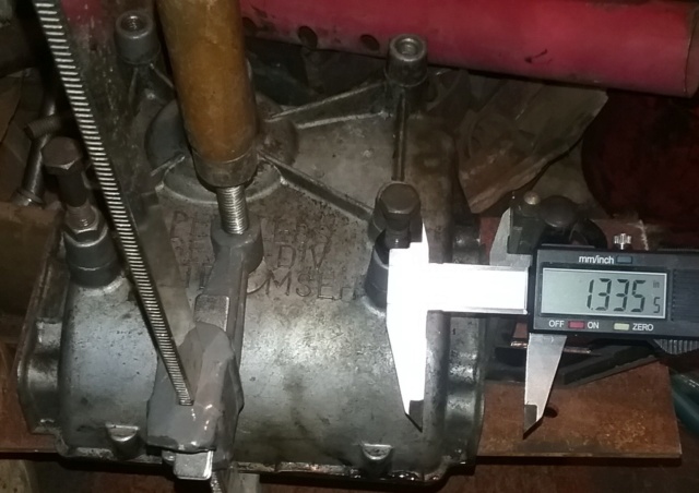 Now to place the bolt pattern onto the case on how far forward on the case is simple. The boltholes over the output shaft has the same center line, meaning they are directly over the output shaft to give you a starting point on how far forward to start the pattern on the bottom case. 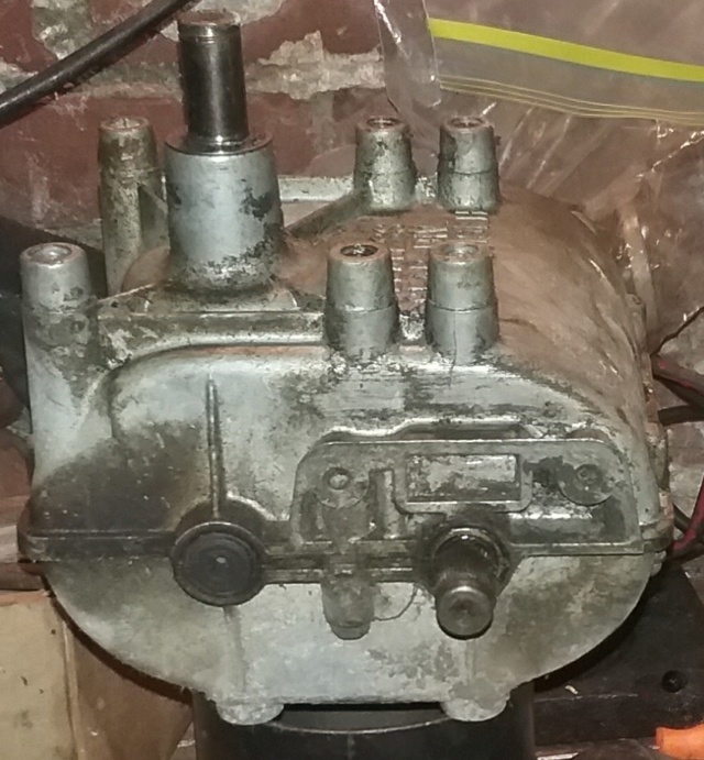 Here is the blueprint of how tall the mounting surface is. To get this measurement, I layed a ruler across 2 boltholes to extend the mounting surface off to the side of the case and then down to the plate steel the case was sitting on. For the measurement, it was the reading on the caliper - the thickness of the ruler = 2.998" 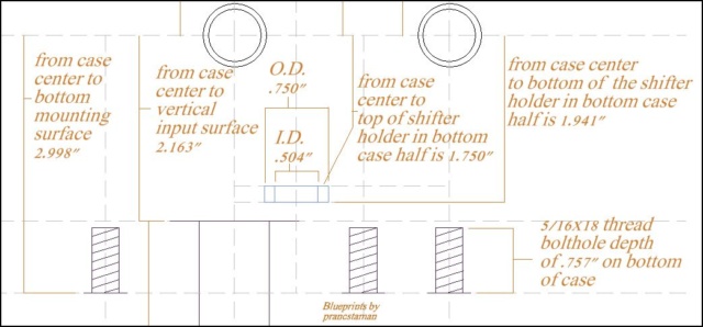 Here is something not in the blueprints. The vertical input shaft bore tapers and this is the measurement of the taper at the point when it goes through the mounting surface. The hole needs to be this size or bigger for the bore housing to fit through. I layed the ruler on the mounting boltholes and took a measurement of the bore housing where the ruler was at. 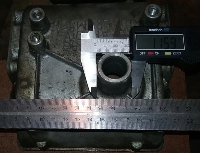 I compared Thunderdivine's mounting pattern with my blueprints, they don't match. I figure I should mention that. Maybe something got lost in converting over to inches from metric. Haven't checked that part yet. That's it for now. More in a couple days. | |
| | | | prancstaman
Veteran Member
Join date : 2015-02-02
Points : 4888
Posts : 1412
Location : Cleveland,Ohio
| | Subject: Peerless 700 blueprint part 9 March 10th 2019, 11:27 pm | |
| Hay People, Now for the vertical input shaft bore. Finalized it tonight by rechecking everything. Pretty much how it's been going before I post something. Lets get to it. Blueprints for the vertical input shaft bore.  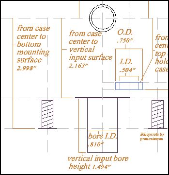 Need 2 measurements for a location, which is front to back of the case, and side to side of the case. The first measurement would be front to back of the case and that is easy. Was mentioned in an earlier post. The vertical input, the gear for this shaft has straight cut teeth on it. For proper mesh of the gearing would mean that the shaft is directly under the horizontal input shaft (counter shaft). Which means they are in line, one straight above the other. Pretty easy. More on the counter shaft later.... Which leaves how far from the side is the bore. To make this easy to measure, I made a jig from a piece of black pipe which was rather rusty to start with. Needed this jig to raise the bore inside of the case high enough to the bushing stops and fit perfectly so it don't wobble while I used it. I had to take this pipe to my job to use the lathe to cut out what I needed. Went pretty easy. Here is the jig I made. One side needs to fit in the bore of .810", so one end of the jig is at .808". The other end just needs to be any diameter to find the center of it. I tried to cut this end to an even measurement to make the math part easy but didn't work, it is what it is. The diameter of this end is .796". 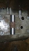 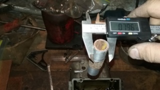  I'll be using the bushing stops as a starting point again. Here is a pic of the bushing stops for the counter shaft and the distance from one bushing stop to the other bushing stop. 5.536" 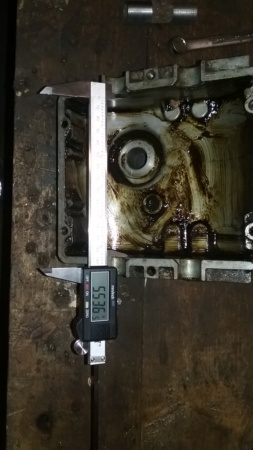 I put the jig into the case and start measuring. From the short side, bushing stop to the jig side is 1.470" 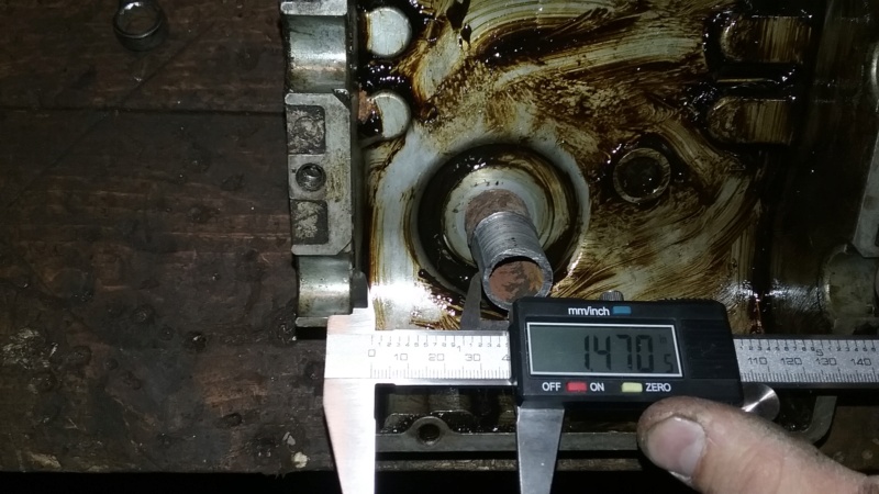 From the wider side, bushing stop to the jig side is 3.270"  The diameter of the jig is .796". Add all 3 of the measurements together. 1.470" + 3.270" + .796" = 5.536", which is the measurement from bushing stop to bushing stop. With these numbers, you can find out how far to the side the bore center is. But first you need to know the center if the jig which is .398". Now the jig is halved up with the number .398", then one side measurement of 1.470", and the vertical input bore center is 1.868" from the bushing stop on the short side. And the other side, .398" + 3.270" = 3.668" from the bushing stop on the wider side to the vertical input bore center. The bore center is figured out, next are the heights. The heights start from the case half milled mounting surface. Here is where the imperfections of a production unit bite ya in the rear. When I set it on the flat steel plate, well, the case half rocked just a bit. The surface was not flat from tightening the case half bolts, and the bushings not fitting in the cases in a perfect way which mean the bushings were a tad big for the bushing bores. So when someone tightened the case halves up together, that warped the surfaces where they joined together. Which is why the case half rocked when it was sitting on the flat steel plate. The thing worked before I took it apart, it will work after I put it together too. No sence to fix a very minor imperfection for it to might do it again. Remember, the quality control people of Peerless knowing the words "Good Enough", LOL, which is fine. Got to understand that, to get units out the door. This is going to explain the heights and what the outcome is for it. Some might agree and some might disagree, but this is how it is. Now back on topic.... For the heights, I'll start with the over all height. Measured from the top of the bore milled surface down to the flat steel plate. Note that I have a clamp holding down the case to the steel plate. This helped to deal with the case being warped on the mounting surface by pushing down on the case so it will flex back into shape, well mostly. Overall height is 3.657"  Next is to divide this number up to get the top of the bore location and the bottom of the bore location only. I flip the case over to measure from the case half mounting surface to the inside bottom of the bore milled surface. By the way, this milled surface is used for shimming of the vertical input shaft gear. Remember the washers, LOL. Anyway. I lay my ruler across the mounting surface and drop the caliper depth gauge down to the milled surface. Need to figure out the correct measurement with an equation which is, the caliper reading - the ruler. So the caliper reading is 3.171" - the ruler is 1.008" wide. 3.171" -1.008" = 2.163". It is 2.163" from the bottom case half mounting surface to the bottom of the inside milled surface on the vertical input bore.  You can figure out the bore length from what is measured so far, but I'll do it anyways. This is the part on how I double checked things so to make sure the numbers are right. I just set the top of the vertical case bore on the flat steel plate and dropped the depth gauge down the hole till it stopped, that simple. Got a reading of 1.494" 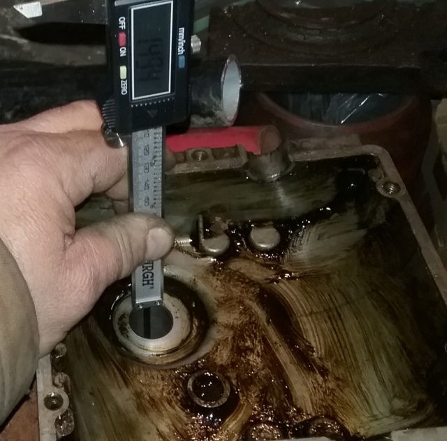 Add up the 2 last measurements, 2.163" + 1.494" = 3.657" The overall height of the vertical input shaft bore. OK. All is good. This next pic is to double check the overall height of the vertical input shaft bore. This is where the imperfections of a production unit get you. Plus if you look back through this thread on the blueprints and in the pics, you can see others too. Numbers close to an expected number but is off by just a wee bit. On this post it just happens to be on a major part of the case, with the case half being just a wee bit warped. With that said, I measure the vertical input shaft bore height a different way to confirm the measurements. I have the case just sitting on the steel plate this time with no clamp, I lay my ruler across the top milled surface to extend the surface over to the side, put the caliper on the ruler, and drop the depth gauge to the steel plate. Get a reading of 4.663". Now to get the correct measurement with an equation. Caliper reading - the ruler width, so 4.663" - 1.008" = 3.655". This measurement is just .002" off. This is OK. If you ever looked at a feeler gauge at the .002" feeler then you would know that it is like foil. 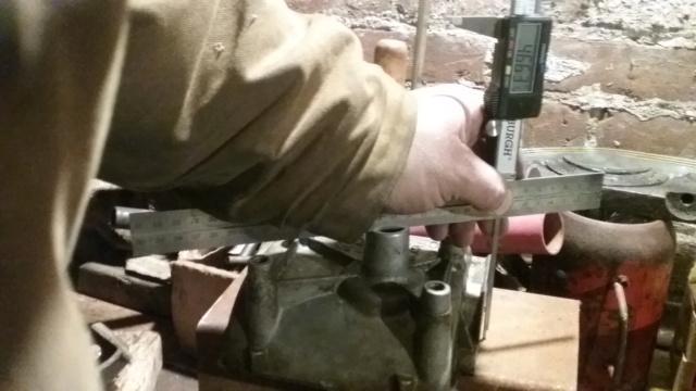 Last pic. Bore inside diameter. .810" 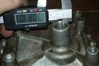 I figure I would mention and show first hand the imperfection thing now. Looking at the numbers and wondering why isn't the number this, wouldn't it be easier to make it like this instead of making it like that. Remember, this is a gearbox out of a production riding mower. Your thinking is correct too. Me, after doing the work and learning about this gearbox, can come up with an educated guess of yes it would, and yes they are. I'm pretty darn sure, LOL. on the original blueprint, the measurement is what you think it is suppose to be. But on my blueprint and with my production gearbox, the measurement is what it is and the unit worked fine before I took it apart. As for what I am using to do the work, 2 Harbor Freight Vernier Calipers, a plate of steel from who knows what, a couple of scrap pieces of steel made into jigs, and doing the work in my basement of a 100 year old house, well, I think they are doing pretty good so far, LOL. Next post will be the shifter holes in the case, maybe tomorrow, maybe, LOL. It's bed time, Later People.......  | |
| | | | Double W Cross Ranch
Veteran Member

2018 Build-Off Finalist
2018 Build-Off Finalist
Age : 20
Join date : 2017-06-09
Points : 5284
Posts : 2640
Location : Literally Nowhere, Texas
| | Subject: Re: Make your own transmission? March 10th 2019, 11:35 pm | |
| I've been trying to keep up with this, but seriously I'm just freakin lost LOL. It'll have a really nice final product I'm betting! Nice work! | |
| | | | prancstaman
Veteran Member
Join date : 2015-02-02
Points : 4888
Posts : 1412
Location : Cleveland,Ohio
| | Subject: Re: Make your own transmission? March 11th 2019, 6:04 pm | |
| - Double W Cross Ranch wrote:
- I've been trying to keep up with this, but seriously I'm just freakin lost LOL. It'll have a really nice final product I'm betting! Nice work!
Are you having trouble with the words on what they mean, like "hole location", then there is the math part. I can explain it differently too. | |
| | | | Double W Cross Ranch
Veteran Member
2018 Build-Off Finalist
2018 Build-Off Finalist
Age : 20
Join date : 2017-06-09
Points : 5284
Posts : 2640
Location : Literally Nowhere, Texas
| | | | | prancstaman
Veteran Member
Join date : 2015-02-02
Points : 4888
Posts : 1412
Location : Cleveland,Ohio
| | Subject: Re: Make your own transmission? March 11th 2019, 6:38 pm | |
| - Double W Cross Ranch wrote:
- I'm probably just too dumb to figure it out lol
Nonsense, what are you having trouble with? | |
| | | | Sponsored content
| | | | | | | Make your own transmission? | |
|
Similar topics |  |
|
| | Permissions in this forum: | You cannot reply to topics in this forum
| |
| |
| | Who is online? | In total there are 30 users online :: 1 Registered, 0 Hidden and 29 Guests IfitaintbrokeMost users ever online was 412 on January 7th 2023, 7:59 am |
|