| | | Homemade tools and stuff from junk laying around |  |
|
+11CraftsmanQuad19 TourMax muckmudd AllisKidD21 MightyRaze frostypaws RichieRichOverdrive MatthewD TheBeal Crazy_Carl prancstaman 15 posters | |
| Author | Message |
|---|
Crazy_Carl
Veteran Member

2018 Build-Off Entrant
2018 Build-Off Entrant
2024 Build-Off Entrant
2024 Build-Off Entrant
Join date : 2017-10-30
Posts : 2561
 | |   | | prancstaman
Veteran Member

Join date : 2015-02-02
Points : 4979
Posts : 1412
Location : Cleveland,Ohio
 |  Subject: Re: Homemade tools and stuff from junk laying around Subject: Re: Homemade tools and stuff from junk laying around  October 6th 2018, 8:39 pm October 6th 2018, 8:39 pm | |
| - Crazy_Carl wrote:
- A sticker?! oh jeesh
Yup, a sticker. Gone now. If I need a weird angle off the table now, I'll use a protractor and a piece of paper, be more accurate. I got another drill press but it has a sticker there also but with a better table. Same brand name. | |
|   | | frostypaws
Member


2014 Build-Off Entrant
2014 Build-Off Entrant
Age : 29
Join date : 2012-07-01
Points : 4572
Posts : 131
Location : iowaaaa
 | |   | | prancstaman
Veteran Member


Join date : 2015-02-02
Points : 4979
Posts : 1412
Location : Cleveland,Ohio
 |  Subject: Re: Homemade tools and stuff from junk laying around Subject: Re: Homemade tools and stuff from junk laying around  October 6th 2018, 9:10 pm October 6th 2018, 9:10 pm | |
| 20 ton, lol. Quit adding a zero, LOL. I got a 2 ton bottle just kicking around in the basement I'll be using. I am overbuilding though for when I actually buy one. The upgrade will happen when I need too but I don't think it will happen because the work I do isn't too heavy. I'll just be doing U-joints, bearings, and stuff like that. 2 tons should be plenty. | |
|   | | prancstaman
Veteran Member


Join date : 2015-02-02
Points : 4979
Posts : 1412
Location : Cleveland,Ohio
 |  Subject: Hydraulic press Part 2 Subject: Hydraulic press Part 2  October 9th 2018, 12:03 am October 9th 2018, 12:03 am | |
| Hay People, Back to the hydraulic press. This will be a short post because I got up late to work today and I want to go to bed early tonight, LOL. I left off on having all the frame pieces of the press cut up. Time to start building the frame. One thing I noticed through the years building anything is that the hardest thing to make is a box. Everything has to be perfect, all the angles, corners, and straight pieces got to be right on for everything to be square. There are certain ways I found to do this to ensure it is done right, with a little cheating to, LOL. I'll start off with the legs. So I grab one leg of the press frame to start off with. A 2 feet long piece. Believe it or not, everything for the frame, all the measurements, holes, angles, and so on from this point on will be based off of one thing, A 1/4 inch hole in the center of this one leg. It will all make sense later. So the best I can, with a Stanley tape measure I find the center of the leg, center punch it, and drill it with a 1/4 inch hole. 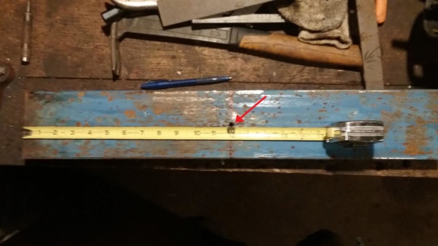 I need a way to mark all the holes on the legs, which are for bolting the top for the hydraulics, the adjustable table, and the feet. I need everything to be square for this to work right and not blow up anything. That's right, NOT blow up anything. Over 20 years working on a press, Yup, I blew up stuff, accidentally ofcourse, LOL. Parts can shoot out like a bullet and hurt someone. I even got metal still in my arm from a mishap years ago. On one of my presses at work, I use a real armored plated cup for protective gear on one of my presses. I will use a method tried and true for me. A template made from a family size Ritz cracker box. Why you ask, a Kraft macaroni and cheese box is too small, LOL. I need a template that will last the build and the poster board the box is made from does the trick. I fold it over the leg's side and crease it, flatten it out and draw lines with X's to mark the hole locations for only a 1/4 of the leg. This template will be flipped over and upside down in all the areas needed to mark every hole on both legs. Doing it this way ensures the hole on one side of the leg will be level with the hole on the other side of the leg. It has one flaw that will be said later on though. The hole locations will be center punched through the template onto the legs for accuracy, then pilot drilled with a 1/4 inch drill bit on my drill press. OK. Now I need a reference point for all the holes and that reference point is the 1/4 inch hole I drilled in the first leg earlier on. The template also has a bolt that fits in this hole on the leg, and by moving the template around and using the hole for a reference point ensures accuracy of every hole on the legs. Note the red arrow for the center of the leg as the reference point. 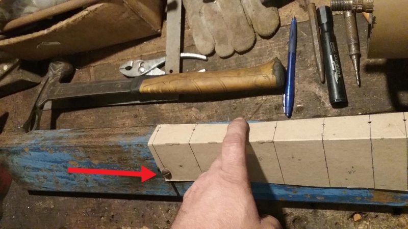 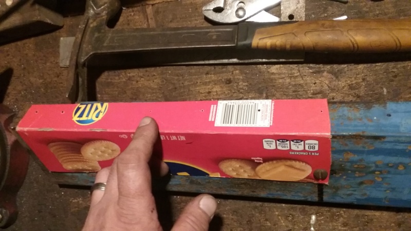 After marking the holes, I transfer the center hole onto the other leg by setting one leg on top of the other leg and then drilling it. Then continue marking the hole locations with a center punch on the 2nd leg. 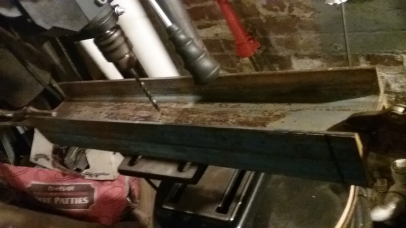 After marking all the holes, I drill all the marks with a 1/4 inch drill bit. That's it for tonight, Later................. | |
|   | | prancstaman
Veteran Member


Join date : 2015-02-02
Points : 4979
Posts : 1412
Location : Cleveland,Ohio
 |  Subject: Hydraulic press Part 3 Subject: Hydraulic press Part 3  October 9th 2018, 11:24 pm October 9th 2018, 11:24 pm | |
| Hay People, I'm back. So, I left off drilling all the holes in the legs with a 1/4 inch drill bit. I just happen to have a bunch of 1/4 inch rod laying around and I stick the rod through the holes. Slides through both holes. Not bad for drilling each side independently. I did nothing to align the holes, not even running the drill bit through both sides at the same time to make a path through them for the rod. In the pic I lay a carpenter square on the rod, Looks good to me. Both legs. 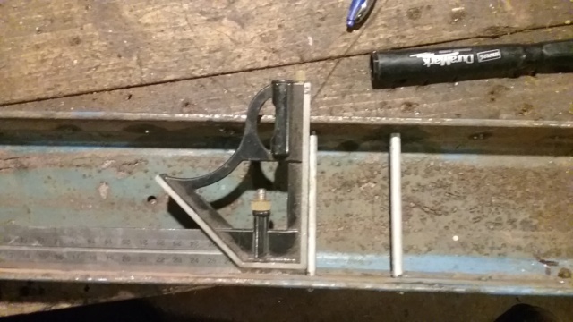 Other leg. 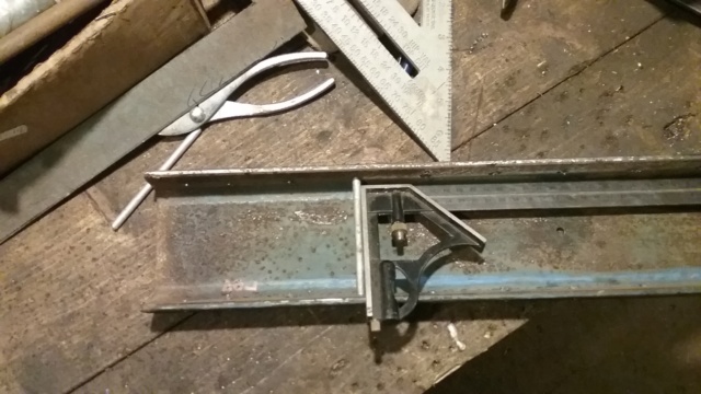 OK, I mentioned in a earlier post that the template idea has a flaw. I'll show that next. This is not a perfect way of doing this but the part that matters worked like a charm. The flaw is that the holes when you look at the side of the leg are not in a straight row. The holes are at the right heights when you use the bottom or top as a reference, but if you use the side of the leg as a reference then the holes are at different spots compared to the one next to it on either side. Doesn't matter though, I was after the same heights of the holes and not that they lined up looking up or down it. Pic shows the flaw. If I would have drawn the template a little better I am sure this would have been better. 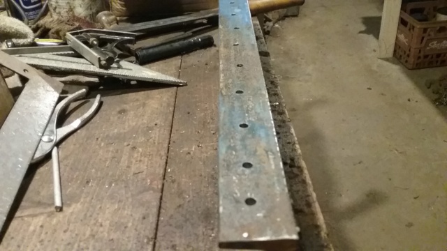 Here is an inside view of the C channel with a rod in place, you can see that one side is in a different spot then the other side. But when I stand the leg up the rod comes out at the same heights on both sides and is level which is what matters for the table to sit on. 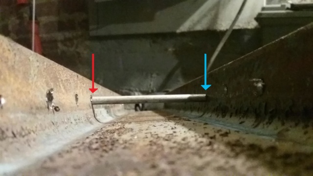 So the legs have all the holes in them. Next are the feet and the top. I start with the top. I grab the angle iron out of the milk crate and get to work. The part that butts up against the legs, I use the template to mark the holes. Lay the template on and use the last 2 hole locations and mark with a center punch on one side and then flip over the template for the other side of the angle iron and mark those hole locations. This first piece of angle iron will be setting the spacing on how far apart the legs will be. I mark both sides using the template with the angle using the edge of the angle iron for a reference so when the pieces are fitted together they form the corners (90 degrees). It matters how I lay the template on the angle iron, had to really think about how the pieces fit together, where the holes are, which side is which on the parts, in reference to the template and how I lay the template on the angle iron. I do it wrong on the other end where the feet go, This side I am working on now is the top for the hydraulics to mount to. 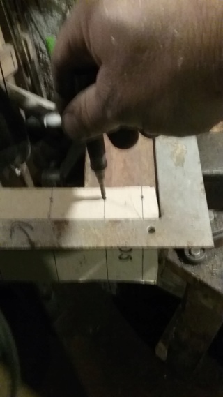 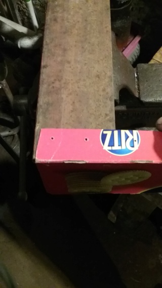 I drill the holes and check for squareness. Looks good. 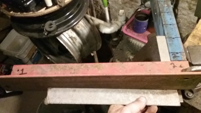 How the template works, I know the holes for the other side are in the same spots, so I cheat. I butt the pieces together and dill the other side. 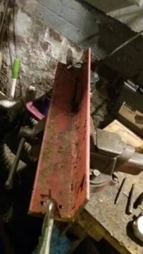 I have both sides of the angle iron for the top of the frame drilled. Now for a little mock up to see how I did. I'll post pics of the mock up next. Everything is drilled with 1/4 inch holes, and there are rods and bolts fitted in all the holes for the mock up.  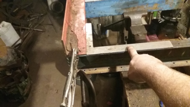 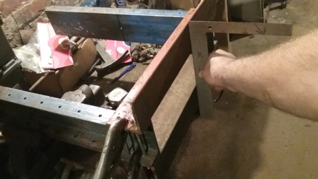 I drill the holes for the top with a 1/2 inch drill bit for the bolts to be used. I dig through the hardware for bolts and find enough of 1/2 inch bolts that are 2 1/2 inch long. I want the shank of the bolts to be used for aligning the pieces, not the thread part of the bolt because threads crush easy. I use bigger nuts as spacers and then the nuts. Bolts are grade 8. 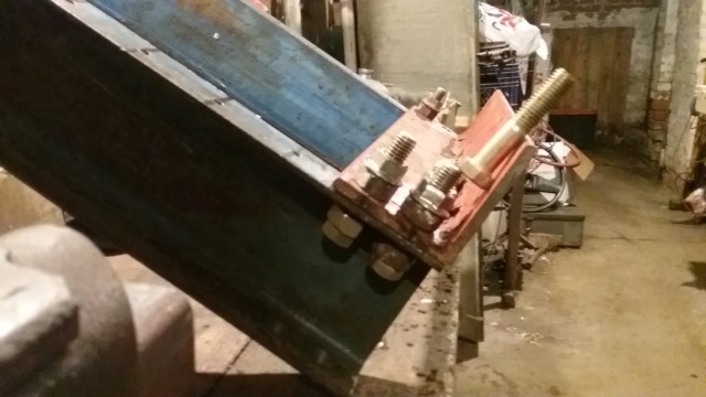 So, the top is complete I tighten the 1/2 bolts up and set it on the bench, lay a square on it to show how it came out. You be the judge...... 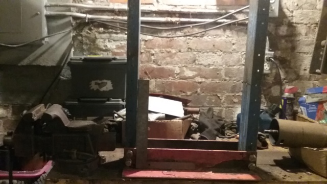 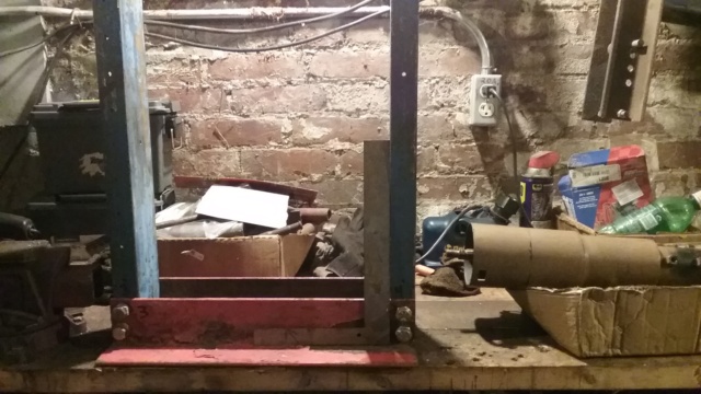 Next post will be of the feet. Later............. | |
|   | | MightyRaze
Administrator


2017 Build-Off Finalist
2017 Build-Off Finalist
2018 Build-Off Top 3 Winner
2018 Build-Off Top 3 Winner
2019 Build-Off Top 3 Winner
2019 Build-Off Top 3 Winner
2021 Winner of Winners
2021 Winner of Winners
1st Place Build-Off 2022
1st Place Build-Off Winner 2022
10,000 POSTS!
10,000 POSTS!
2024 Build-Off Entrant
2024 Build-Off Entrant
Age : 49
Join date : 2016-09-06
Points : 15341
Posts : 10809
Location : Oklahoma
 | |   | | prancstaman
Veteran Member


Join date : 2015-02-02
Points : 4979
Posts : 1412
Location : Cleveland,Ohio
 |  Subject: Re: Homemade tools and stuff from junk laying around Subject: Re: Homemade tools and stuff from junk laying around  October 9th 2018, 11:59 pm October 9th 2018, 11:59 pm | |
| - MightyRaze wrote:
- Quite a bit of progress today.
Thanks Mighty. As far as the actual hydraulic press goes, I have the frame complete and have one leg to go for drilling the 1/2 inch holes for the table adjustment on the legs. That's alot of drill, WOW. | |
|   | | AllisKidD21
Moderator

2020 Build-Off Entrant
2020 Build-Off Entrant
1st Place Build-Off 2019
1st Place Build-Off Winner 2019
Age : 25
Join date : 2016-07-10
Points : 8470
Posts : 5190
Location : Ontario Canada
 |  Subject: Re: Homemade tools and stuff from junk laying around Subject: Re: Homemade tools and stuff from junk laying around  October 10th 2018, 12:22 am October 10th 2018, 12:22 am | |
| Looking good so far prancstaman! Should be heavy duty enough for sure, came out looking nice and square too. I bet drilling all those adjustment holes got a bit boring after a while.   "This'll either wake you up or put you to sleep forever!"- Red Green "Whatever you do you should do right, even if it's something wrong." - Hank Hill - MTD Off-Road Build
- Ford LT 110 Off-Road Build
- Craftsman GT 6000 Off-Road Build
- Sears LT11 Rat Rod Build *2019 Build-Off Winner!* Garden Tractor Collection: Allis B-110 x2, 710, 716, & 410 - Wheel Horse 655, 953 & 500 Special - Case 444 - Bolens Versamatic, G10 & 1668 Diesel Swapped - Cub 106, 124 & 1000/149 Frankentractor - Ford 120, LGT 125 & 145 - White 1650 Yard Boss - Moto Mower 710-100 | |
|   | | prancstaman
Veteran Member


Join date : 2015-02-02
Points : 4979
Posts : 1412
Location : Cleveland,Ohio
 |  Subject: Re: Homemade tools and stuff from junk laying around Subject: Re: Homemade tools and stuff from junk laying around  October 10th 2018, 5:30 pm October 10th 2018, 5:30 pm | |
| - AllisKidD21 wrote:
- Looking good so far prancstaman! Should be heavy duty enough for sure, came out looking nice and square too.
I bet drilling all those adjustment holes got a bit boring after a while.  Thanks. Should be able to handle up to 10 tons easy. When it gets a BIT BORING, LOL, I crank up the MP3 player. Makes the time go quicker. | |
|   | | prancstaman
Veteran Member


Join date : 2015-02-02
Points : 4979
Posts : 1412
Location : Cleveland,Ohio
 |  Subject: Hydraulic Press Part 4 Subject: Hydraulic Press Part 4  October 12th 2018, 8:09 pm October 12th 2018, 8:09 pm | |
| Hay People, I'll finish off the frame in this post. I guess I messed up on using the template but was no big deal. I did the marking of the holes different probably from being tired from everything. More on this later. I start off by laying 1 piece of angle iron on the legs in it's place, drag it down till I see the hole and mark it on the angle iron. I place it back, then drag it to the side to mark the hole. The end result is an X for the spot. Both feet are in reference to the X. The heights, corners, and being square in the frame are off the X. 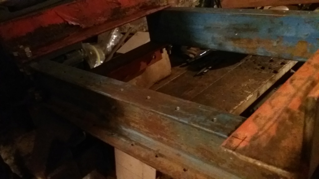 So here is where I made the mistake. I lay the angle iron back in it's place on the legs, then lay the template over the angle iron and mark the holes for both sides. I guess because the template wasn't flat, the holes didn't line up from the angle iron to the legs. They are off a little bit for some reason. Maybe I had the template folded wrong? Who knows. All I needed was the holes to be somewhat lined up to drill the bigger hole. 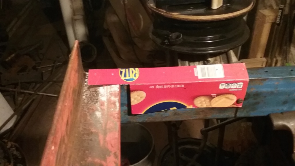 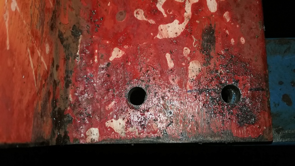 I cheat by butting the 2 pieces together to drill the pilot holes , They was all off a little. Oh well. I Square up one foot and clamp it in place. I have to hold this whole frame on the drill press table to drill the holes. 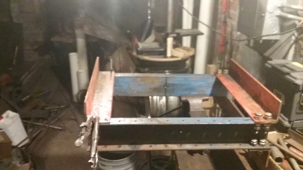 I last 2 holes, one on each side for the first piece. I set it on the floor to drill the rest by hand. I drill the 6 remaining holes on the floor. Easier then I thought, LOL. So, the holes being off didn't matter because the thickness of the steel kept the bit going down straight and not veer off to the side. As long as the drill bit hit the pilot hole I was happy. And the drill bit drilled away the whole pilot hole too. How's that for fixing a mistake. 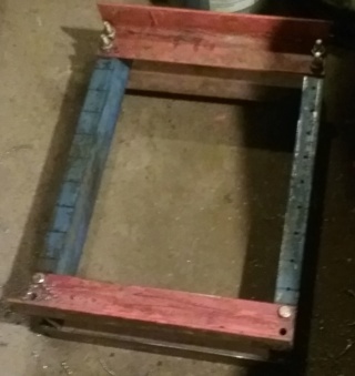 I had to buy bolts and nuts. 8 grade 8 bolts and a box of 50 1/2 inch x 13 nuts. = $20 spent so far on this. 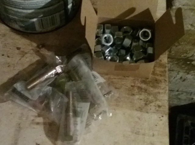 I bolt the feet on and check for squareness. 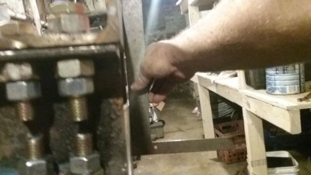 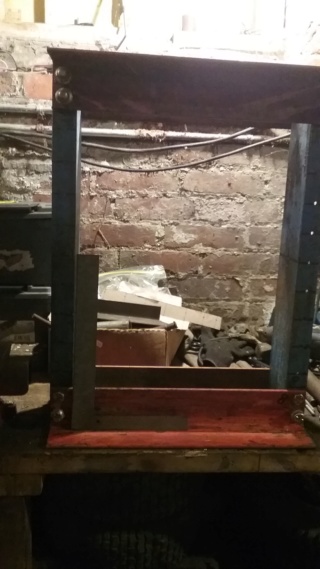 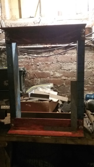 I finish off the frame with drilling the holes for the adjustments for the table. I drill each side and then I run the drill bit through both holes so a rod can slide through. In the pic I am using a 1/2 inch rod to slide through the 1/2 inch holes. I want to make sure they are aligned. I will buy 7/16 rod for when I use the press. If I use 1/2 inch rod while using the press and it should happen to bend then it will not come out. Loosy goosy never got stuck, LOL. 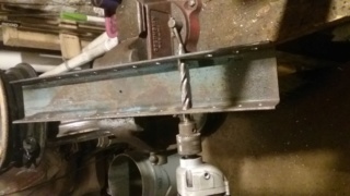 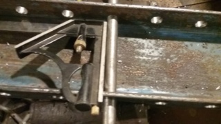 There it is. What a pain but it is square.  | |
|   | | prancstaman
Veteran Member


Join date : 2015-02-02
Points : 4979
Posts : 1412
Location : Cleveland,Ohio
 |  Subject: Hydraulic Press Part 5 Subject: Hydraulic Press Part 5  October 14th 2018, 12:24 am October 14th 2018, 12:24 am | |
| Hay People, So I got the frame done, next is the table. I'm making the table out of the C channel. I'll probably make another table from the angle iron later, but for now this will do. 18 inches wide to span the width of the frame to the edges. Mark the inside of the legs on the table parts. I want the bolts to be right next to the legs so the table doesn't kick to the side while using it, remember me saying stuff blowing up, LOL. So I make my marks 1/4 inch in for the pilot holes and drill them. 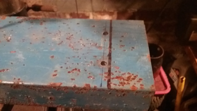 Time to cheat a little. I set the other leg on top and clamp it to the other, flip it to drill the holes. 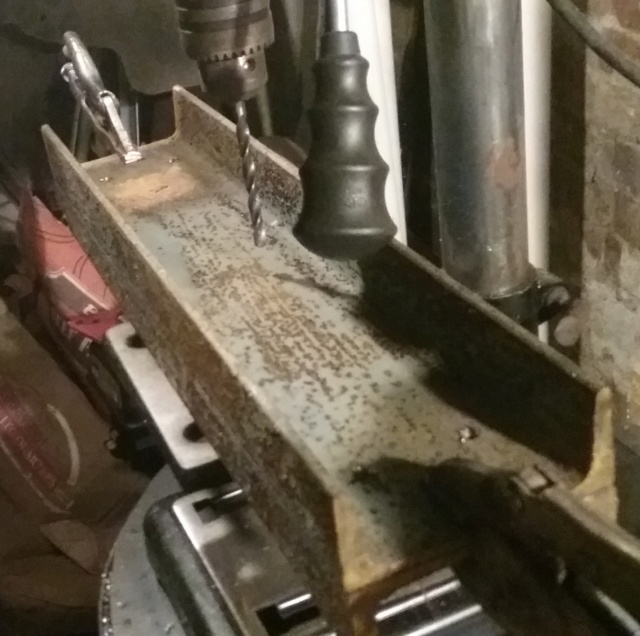 I drill the 1/2 inch holes for the bolts and test fit the table in the frame to check fitment. 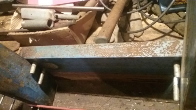 I set the legs together and fit bolts through the holes to check alignment of the holes. Then I mark the pieces. If you are wondering about the marking of the parts is because every hole is in a different spot which means this hole thing will only go together right one way. So every joint, connection, and corner gets a marking. Either numbers, lines, or words. I will remark it afterwords with carvings in the steel so I can sand and paint this later. 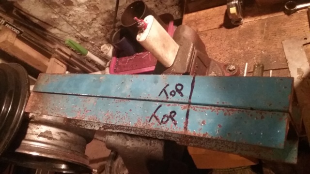 So, I buy more stuff. 4 bolts for the table and 2 pieces of threaded rod for the hydraulics. These 6 pieces cost $28. The total for stuff I bought total $48 so far. And I only bought hardware up to this point. WOW!!! 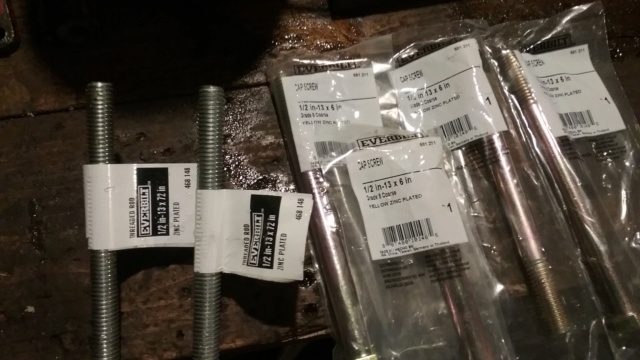 I check the bolts to see if they will work. They are grade 8 bolts. At Home Depot, the regular bolts have threads just about all the way to the head of the bolt. I didn't like that because the structure of the parts would be sitting on the threads which would damage them. The grade 8 bolts have the shank most of the span of the bolt with 1 inch for the threads. So grade 8 bolts it is. I don't even bother to get the grade 8 nuts, cost to much for how many I need and they don't even stock that many. If the regular nut strips then the nut will only be damaged, then switch it out and put 2 there. That simple. 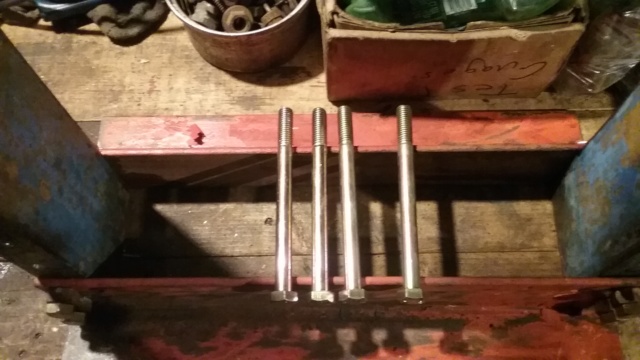 Starting to look like something now. 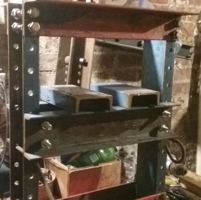 OK. I'll show the hydraulic part that will be doing the pushing. It is on another old tool I made for breaking beads on tires that I used for a couple years and originally bought this jack to pull a dent out of my jeep. I think I had this jack for about 15 years so far. Just a little 2 ton bottle jack that has been sitting around for a while now. Figure I would use it for this. Pretty small but 2 tons is a lot of force from this dinky thing. It's only temporary, I'll be upgrading later, which explains the overbuilding of the parts for the press. 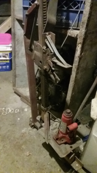 Later................. | |
|   | | prancstaman
Veteran Member


Join date : 2015-02-02
Points : 4979
Posts : 1412
Location : Cleveland,Ohio
 |  Subject: Hydraulic press Part 6 Subject: Hydraulic press Part 6  October 16th 2018, 9:36 pm October 16th 2018, 9:36 pm | |
| Hay People, Yet another installment of "Homemade tools and stuff from Junk laying around"  So I left off with the frame built and got the adjustable table on the frame. This post will be on the part I use for the ram. The ram is the part that does the pushing, not necessarily has to do with the hydraulics. The ram can be part of the hydraulic cylinder piston that does the pushing, or can be 2 separate parts where the hydraulic piston is on top of the ram bolted together as 2 separate components. On mine, it will be 2 separate components, one on top of the other. I was talking to a buddy at work about it and he said he had this giant bolt but he had to find it though. If he finds it, I'll use it for something, maybe not this but something. I need this up and running so I can use it. Just like the bench grinder. Been using that on this too, LOL. So, I need a ram. So I'm thinking, looking, thinking some more. There is this very old 20 ton bottle jack in my basement and doesn't quite work. The piston moves up but when I was using it on my house, it would bleed down slow. Also leaks on the pump too. I can't even remember where it came from but has been in my basement forever, since we moved here (20 years ago I think). I think this classifies the 20 ton bottle jack as JUNK, LOL. I bet it has a really big piston in it. So I take it apart. Mind you, this is just about a week ago. I haven't really finished working out the details of this build till I finally take this thing apart. 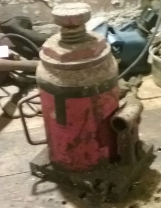 I kiss it with some heat, and starts to sweat, the pain...... Then after some fussin, cussin, and a sledge with pry bar, Bingo!!! Popped the top off. 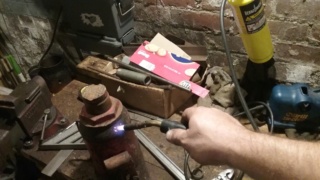 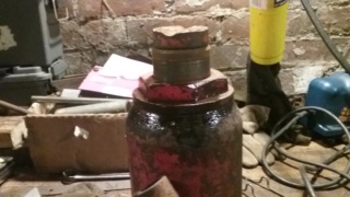 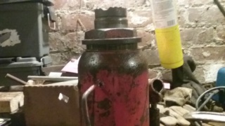 I unscrew the top. Have to figure how to take the piston out, so I pump it. For once it works right. I pump the piston all the way out of it. I don't even make a mess on the bench too. The fluid just dumps back into the reservoir. 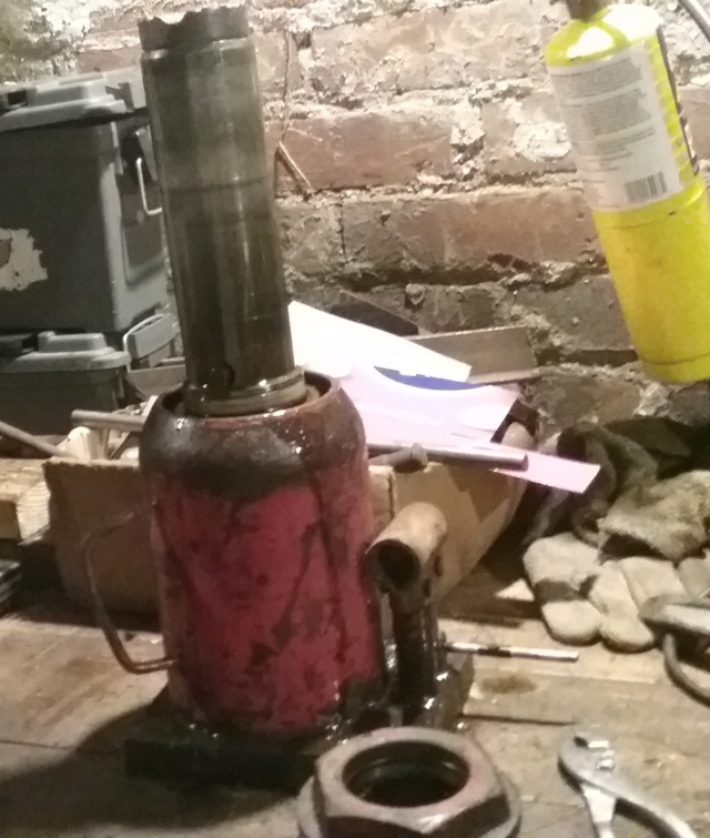 So, now I have a 20 ton extendable ram. The top screw cap will be used as a guide for the ram. I'll tell more on the extendable ram later but I will say that it is a nice high end feature for a press. 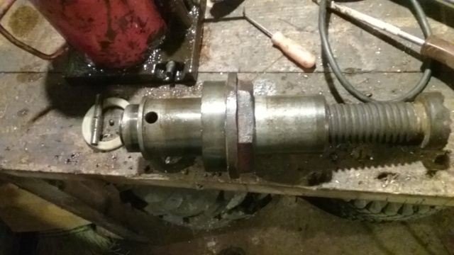 As for the screw cap, it just fits across the 4 inch span on the top of the frame. Then I measure the total length of the ram with the extension screwed out almost all the way. Measures little over 10 inches but call it at 10 inches, need some thread inside the ram so they don't get damaged pushing something. 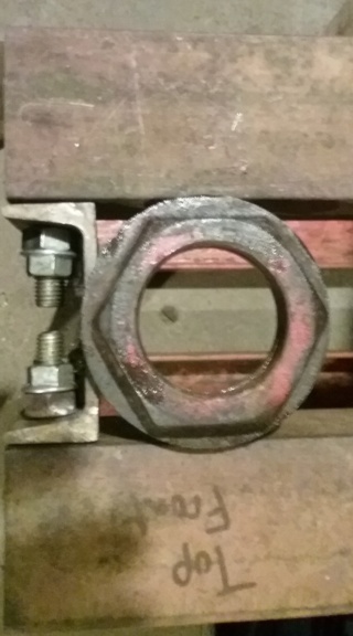 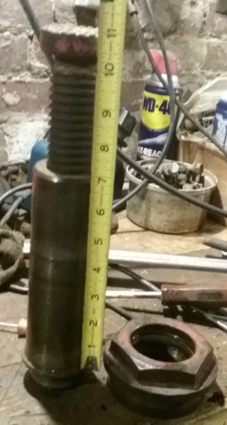 The piston that I will be using as a ram is 2 1/4 inches in diameter and is 3/4's of the way through hollow for the extension to screw down into the piston. 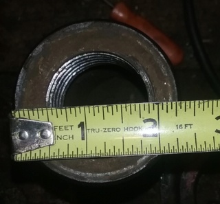 Here are the rest of the parts. I cut the cylinder out of the base plate, it's like 1/2 inch steel and takes 2 cut off wheels. Cut the pump cylinder off with the pump arm brackets too. The big housing (coffee cup lookin thing) will be used for a jig, I'll explain that later too. 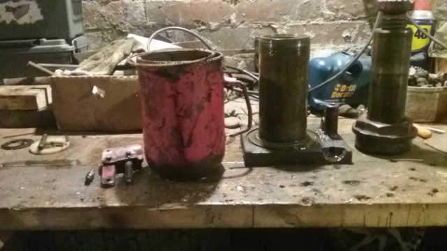 That is what I'll be using for the ram. It will be mounted between the angle iron top. The piston cylinder will be used too, to support the ram as it is moving down and the piston cylinder screws onto the cap. More next post as I start working on mounting the ram. To be continued........................... | |
|   | | prancstaman
Veteran Member


Join date : 2015-02-02
Points : 4979
Posts : 1412
Location : Cleveland,Ohio
 |  Subject: Hydraulic Press Part 7 Subject: Hydraulic Press Part 7  October 18th 2018, 10:27 pm October 18th 2018, 10:27 pm | |
| Hay People, Here's some more..... Time to mount the ram into the frame, so I need some plate steel. My brother-in-law gave me some, 4 pieces that I was going to use for another project. I use 1 1/2 pieces for this. Maybe still enough leftovers for the other project too. Staying with the theme here, been sitting in my basement for about 3 years too. They are 3/16 thick, about 8 inches long, and about 6 inch sides, U-shaped. No clue what they was used for, LOL. 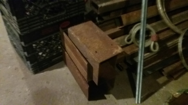 I use one hole piece, find the center for a pilot hole and use a hole saw and drill it out. 3 5/8 inch hole, I was drilling slow so it wouldn't skip out, in doing so made it smoke, or so I thought when I added oil. Turned out being my drill was smoking from over heating. Since the drill was spinning slow, it couldn't cool right. That's OK, the drill still works good. I then grind the burrs out of the hole and fit the cap. 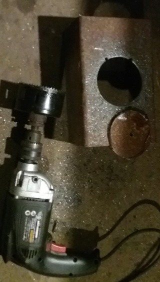 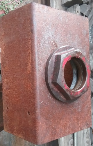 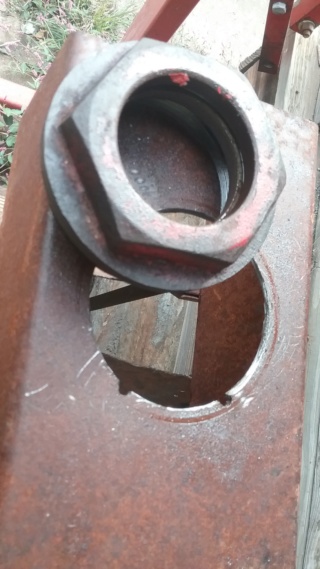 A little mock up of the ram with the cap and cylinder together on the plate. I trim the sides of the plate so it fits under the top angle iron.  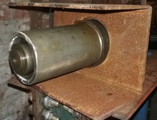 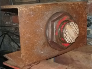 How I plan to mount the ram will be with 6 pieces of all-thread from the plate going up 26 inches, 3 on each side. I want the all-thread spaced apart so I can fit bottle jacks on top. So since I have a 20 ton base plate, I use that to space the all-thread apart. So I can put up to a 20 ton bottle jack in it for the hydraulics part, more on that later. 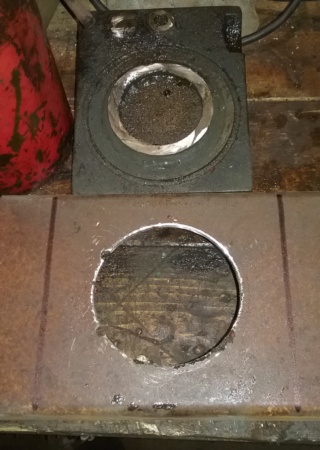 Next, I mark and drill holes for the all-thread, 3 on each side. Then drill the holes 1/2 inch big for the all-thread later. 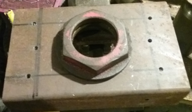 I dig out more junk for brackets, (the angle iron). My junk box on my bench for making quick stuff. I cut up the angle iron into brackets to mount the ram. 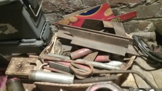 To drill the brackets to match the ram plate so the all-thread passes straight through, I clamp the angle iron to the ram plate and use the 1/2 inch drill bit to mark the holes by drilling it. The tip of the 1/2 inch drill bit is pretty much useless but it will leave a mark which will be the center of the bolt holes. A little cheating never hurt. Is a reliable way of finding the center of a hole too, as long as the drill bit don't move the 2 plates while leaving a mark. So a good clamping is required. As I final drill each hole, I drop a 1/2 inch bolt down the hole to help keep the alignment of the holes for the pattern. So the whole process for one bracket was- clamp, 1/2 inch drill mark, 1/4 inch drilled hole on the mark, 1/2 inch drilled hole, drop a bolt in the hole, reclamp, then repeat on the next hole. 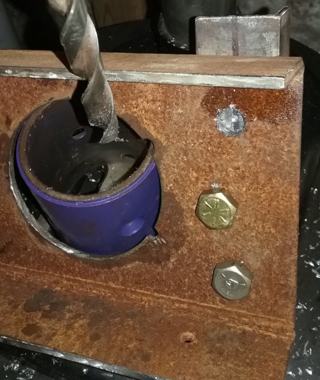 Top view of the done brackets and the ram plate. The holes line up for the all-thread to pass through and with nuts where they need to be on the all-thread to hold the ram and plate in place. 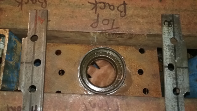 Mock up time. I find 2 bolts to hold this part together. This is the ram, cylinder, cap, ram bracket, top ram brackets, all in place in the frame. 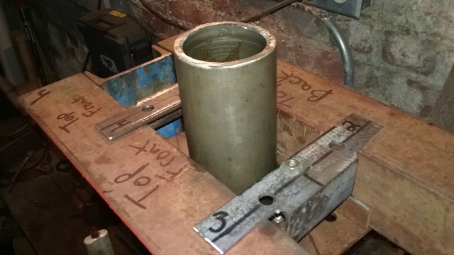 Not bad, not bad at all....... 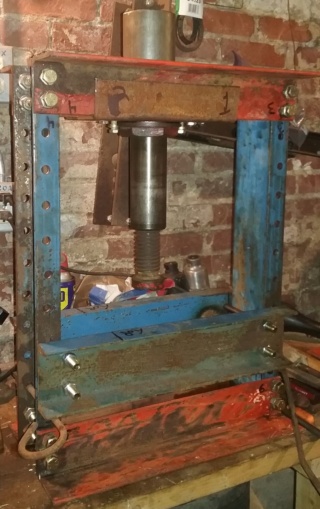 Last pic that I have, and is of the return springs. Need them to be 10 inches tall at least so I'll double stack them and the small ones fit inside the big ones. Should be strong enough to lift the ram and push down the bottle jack. If not, I can get more springs. Yes, I have a spring source, LOL.  That's it for the pics. Cars been breaking so that has been keeping me busy. More pics soon........ Later People | |
|   | | prancstaman
Veteran Member


Join date : 2015-02-02
Points : 4979
Posts : 1412
Location : Cleveland,Ohio
 |  Subject: Hydraulic Press Part 8 Subject: Hydraulic Press Part 8  October 22nd 2018, 9:58 pm October 22nd 2018, 9:58 pm | |
| Hay People, Small post tonight, just 2 pics. I bought more bolts, LOL. I got 2 concrete anchor bolts that are 10 inches long for the adjustable table. Home Depot said they were 1/2 inch thick but a closer look and the shank of the bolts are a tad smaller and the threads only are 1/2 x 13 and the shank steps down a smudge. I think they will work perfect. Long enough and if they ever get bent then they won't be jammed in the frame. Plus they didn't have 7/16 steel rod at all, so I wondered the store checking other sections for something I can use and came across these in the fencing department. $2 each, so the total is up to $52.  I put them in the frame for the table. Just long enough. The table sits only on the shank of the bolts so it will be level with the frame 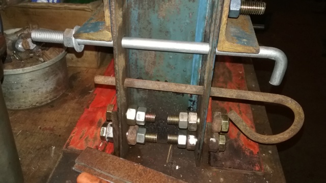 | |
|   | | prancstaman
Veteran Member


Join date : 2015-02-02
Points : 4979
Posts : 1412
Location : Cleveland,Ohio
 |  Subject: Hydraulic Press Part 9 Subject: Hydraulic Press Part 9  October 29th 2018, 9:41 pm October 29th 2018, 9:41 pm | |
| Hay People, Got alot done and plenty of pics, LOL. I'll try to limit the pics since there are 40 of them this time. So, up next is the mounting of the ram and hydraulic workings. Not a perfect setup but does work for now. The threaded rod gets cut up and I make 2 plates, reinforcing plates, and 2 C-channel for the top end. Making the stuff involves drilling 64 holes. Springs, hardware, and bottle jack, make up the hydraulic workings.  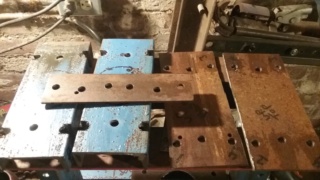 I start mounting the cap for the ram. Use 2 bolts to hold it in place. The plate is thick enough to thread and I put locking nuts on the other side. Then I mount 2 threaded rods on the plate. The 2 threaded rods are shorter then the others and are alignment rods for the working of the top. On the side with the ram cap, I put 2 reinforcing plates for the threaded rods. Note the numbers of the parts for orientation. Just a big puzzle right now. 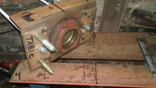 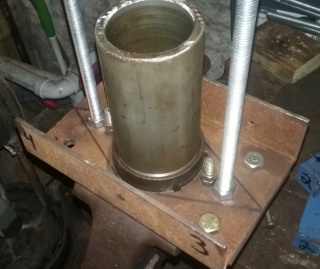 I mount the ram plate on with the holders and start putting the other threaded rods in place. I pretty much suck at puzzles. I put it together wrong. A closer look at the numbers means I put the ram plate on backwards. Took me 2 minutes to figure it out because of the numbers. This orientation thing with the numbers helps with the imperfections of the build. I drilled all the holes right but just put the parts together wrong. Yah, the holes are in the general area needed but not symmetric. 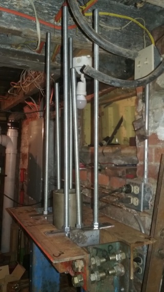  I take it all apart and redo the assembly right this time. 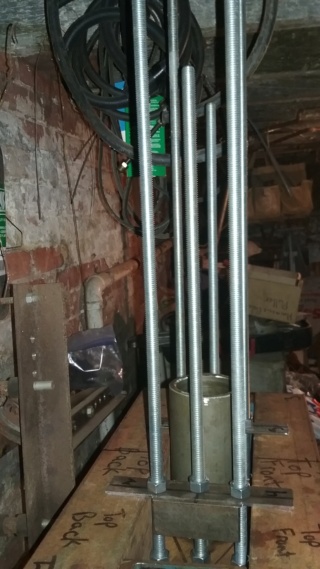 Time to put the hydraulics in. I modeled this thing from one at work, on how it works. So, the 2 threaded rods in the middle are guides for the hydraulic base plate that moves down and pushing the ram down, they also will have the return springs on these 2 rods. The 4 outer threaded rods hold the top plates from moving, and gives the bottle jack something to push on, while grabbing the frame. SO, while the bottle jack is pumped, the base of the jack in being pushed down to move the ram down (not hooked up yet). 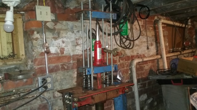 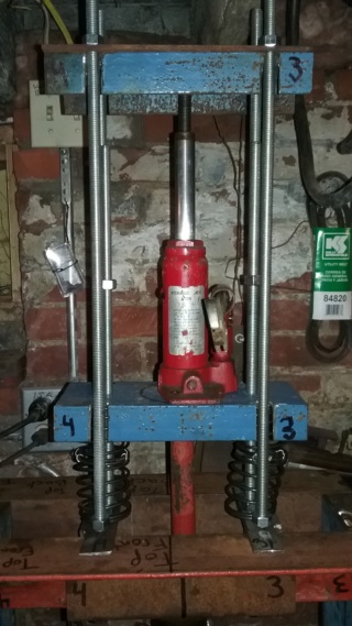 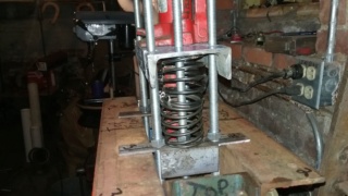 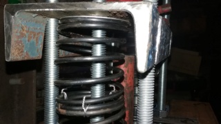 OK, time to connect the ram to the hydraulics. I pull the ram and drill and tap the center of it for a threaded rod to connect to the hydraulic base plate. This threaded rod will be covered with a pipe that will take the force of the pushing (red pipe). Needs to screw together in case something bends. I probably will replace the pipe with something bigger down the road but this will work for now. And put it together. The bottle jack will be sitting on the blue C-channel on top of the disk. The disk is threaded in the center and is the locking nut for the threaded rod too. The nuts on the threaded rod are there to hold the red pipe centered while on. 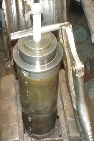 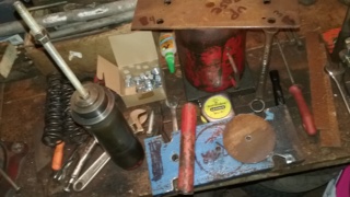 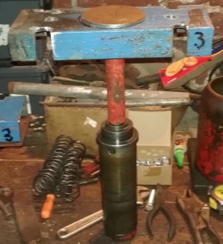 Back together and give it a try. Pretty good reach. I had to use all 8 springs to be able to lift everything back up. 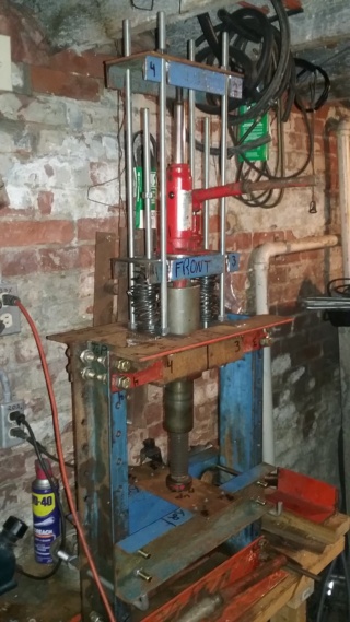 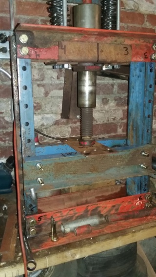 That's it for now. I got it functioning........... Next post in a couple hours. | |
|   | | AllisKidD21
Moderator


2020 Build-Off Entrant
2020 Build-Off Entrant
1st Place Build-Off 2019
1st Place Build-Off Winner 2019
Age : 25
Join date : 2016-07-10
Points : 8470
Posts : 5190
Location : Ontario Canada
 |  Subject: Re: Homemade tools and stuff from junk laying around Subject: Re: Homemade tools and stuff from junk laying around  October 29th 2018, 10:04 pm October 29th 2018, 10:04 pm | |
| Great progress! Cool to see that you got it working.
Do you think it would maybe be easier to have two pull type springs to pull the jack back up?
Also I like the crescent wrench as a jack handle in those two pictures, hahaha.  "This'll either wake you up or put you to sleep forever!"- Red Green "Whatever you do you should do right, even if it's something wrong." - Hank Hill - MTD Off-Road Build
- Ford LT 110 Off-Road Build
- Craftsman GT 6000 Off-Road Build
- Sears LT11 Rat Rod Build *2019 Build-Off Winner!* Garden Tractor Collection: Allis B-110 x2, 710, 716, & 410 - Wheel Horse 655, 953 & 500 Special - Case 444 - Bolens Versamatic, G10 & 1668 Diesel Swapped - Cub 106, 124 & 1000/149 Frankentractor - Ford 120, LGT 125 & 145 - White 1650 Yard Boss - Moto Mower 710-100 | |
|   | | prancstaman
Veteran Member


Join date : 2015-02-02
Points : 4979
Posts : 1412
Location : Cleveland,Ohio
 |  Subject: Hydraulic Press Part 10 Subject: Hydraulic Press Part 10  October 29th 2018, 11:08 pm October 29th 2018, 11:08 pm | |
| Hay People, Back at it. So the press is functioning. A couple odds and ends to tie up now. The very top plate and C-channel have nuts on top of these to make something for the jack to push against but there is nothing under them to hold them in place except the bottle jack. I find a piece of conduit and cut it up to use to hold up the top from the 2 middle threaded rods.  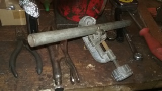 I put a couple nuts on the threaded rods to hold the conduit up against the top part. Then drop a couple bolts down through the top part, since there are holes there to keep the conduit in place and for alignment of the threaded rods. I add the last plate to the top part also. Since the top plates are now supported from both ends, I can remove the bottle jack without anything falling down or out of place. The bottle jack just sits in place. 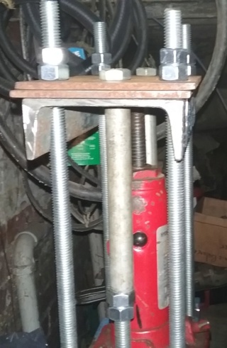 OK. I must have drilled over 150 holes on this thing. Up until now everything fit together nicely. One hole was out of place by a hair, LOL. I took a round file to it to enlarge it. And that was that. 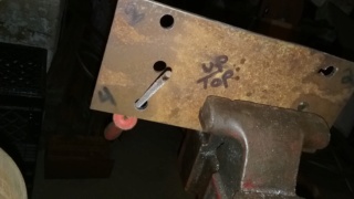 OK, Here's the money shot. I pump up the bottle jack all the way and check the ram. Everything payed off. The ram in the pic is at full extension. I think it looks straight. The red arrow shows it. 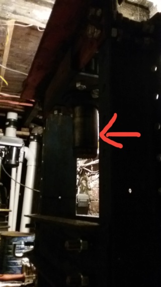 I finish off the table by putting spacers (nuts) on the bolts so the table is tight up against the legs of the frame.  I buy one more thing, another box of nuts for $9. The total is up to $61 I think. Not too bad. 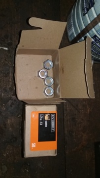 Now I try it out. I got this spindle off my Escort laying around. I want to see if I can take it apart. I mount it up in the press. 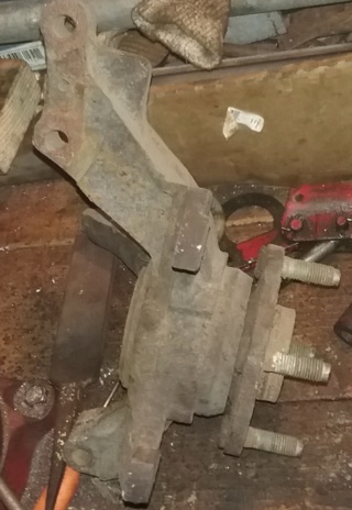 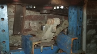 Here is why I wanted the hydraulics separate from the ram. So I can torch the parts when they don't push out. Takes some heat and a lot of pushing but it comes apart. The top plates flex alot but don't bend. I will have to reinforce the top more. Evidently 2 plates of 3/16 inch steel with 1/4 inch C-channel is not enough of steel for the top of this thing. It's only a 2 ton bottle jack too. That will be later. For now I can do light work with it atleast. 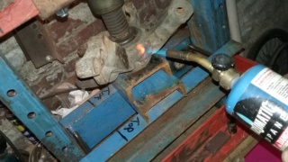 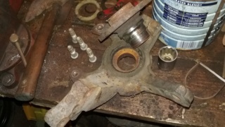 More later. I still need a stand for it and have to reinforce the top more. Then attachments. I got a lot of ideas for the attachments to be able to do way more work. I watched the You Tube videos, they have no clue what to do about how to work a press. Later. | |
|   | | prancstaman
Veteran Member


Join date : 2015-02-02
Points : 4979
Posts : 1412
Location : Cleveland,Ohio
 |  Subject: Re: Homemade tools and stuff from junk laying around Subject: Re: Homemade tools and stuff from junk laying around  October 29th 2018, 11:32 pm October 29th 2018, 11:32 pm | |
| The pull springs would be for the bottle jack being inside the frame and pulling up on the ram. I got the bottle jack up above the frame so I needed to put the push springs on it. Besides, I had no pull springs, LOL. The wrench was something handy because I couldn't find the original handle then. | |
|   | | AllisKidD21
Moderator


2020 Build-Off Entrant
2020 Build-Off Entrant
1st Place Build-Off 2019
1st Place Build-Off Winner 2019
Age : 25
Join date : 2016-07-10
Points : 8470
Posts : 5190
Location : Ontario Canada
 |  Subject: Re: Homemade tools and stuff from junk laying around Subject: Re: Homemade tools and stuff from junk laying around  October 30th 2018, 12:18 am October 30th 2018, 12:18 am | |
| Oh okay, haha. I thought maybe you could have the springs attatch to both of the pieces of blue C-channel, that way they'd pull the C-channel pieces together and close the jack. Just a though, I imagine it works great the way it's set up now.  "This'll either wake you up or put you to sleep forever!"- Red Green "Whatever you do you should do right, even if it's something wrong." - Hank Hill - MTD Off-Road Build
- Ford LT 110 Off-Road Build
- Craftsman GT 6000 Off-Road Build
- Sears LT11 Rat Rod Build *2019 Build-Off Winner!* Garden Tractor Collection: Allis B-110 x2, 710, 716, & 410 - Wheel Horse 655, 953 & 500 Special - Case 444 - Bolens Versamatic, G10 & 1668 Diesel Swapped - Cub 106, 124 & 1000/149 Frankentractor - Ford 120, LGT 125 & 145 - White 1650 Yard Boss - Moto Mower 710-100 | |
|   | | prancstaman
Veteran Member


Join date : 2015-02-02
Points : 4979
Posts : 1412
Location : Cleveland,Ohio
 |  Subject: Re: Homemade tools and stuff from junk laying around Subject: Re: Homemade tools and stuff from junk laying around  October 30th 2018, 8:21 pm October 30th 2018, 8:21 pm | |
| - AllisKidD21 wrote:
- Oh okay, haha. I thought maybe you could have the springs attatch to both of the pieces of blue C-channel, that way they'd pull the C-channel pieces together and close the jack. Just a though, I imagine it works great the way it's set up now.
Yah, I thought of putting the springs up there but the throw of the ram is pretty long and would probably damage the springs stretching , a few inches would work but the throw now is almost the length of the bottle jack minus the base and would give up some of the adaptability for a different bottle jack. Has about a 7 inch throw on the ram but the 2 ton doesn't reach the full movement. Yup fine for now. Plus these springs are free and I can get more free ones too. They can be expensive, LOL. | |
|   | | frostypaws
Member


2014 Build-Off Entrant
2014 Build-Off Entrant
Age : 29
Join date : 2012-07-01
Points : 4572
Posts : 131
Location : iowaaaa
 | |   | | prancstaman
Veteran Member


Join date : 2015-02-02
Points : 4979
Posts : 1412
Location : Cleveland,Ohio
 | |   | | muckmudd
Established Member


2018 Build-Off Entrant
2018 Build-Off Entrant
Age : 21
Join date : 2017-07-11
Points : 3444
Posts : 825
Location : In the shop
 |  Subject: Re: Homemade tools and stuff from junk laying around Subject: Re: Homemade tools and stuff from junk laying around  November 2nd 2018, 12:45 am November 2nd 2018, 12:45 am | |
| I made this out of a chuck that I found at the dump and a free socket. Needed a right angle drill for a project and I didn't have one so I improvised and attached it to my air ratchet and it actually drilled the hole despite the slow speed of the ratchet. 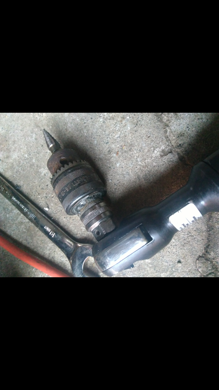 | |
|   | | prancstaman
Veteran Member


Join date : 2015-02-02
Points : 4979
Posts : 1412
Location : Cleveland,Ohio
 |  Subject: Re: Homemade tools and stuff from junk laying around Subject: Re: Homemade tools and stuff from junk laying around  November 2nd 2018, 7:52 pm November 2nd 2018, 7:52 pm | |
| LOL, Now that's cool and perfect for this thread. Thank You for the info Muckmudd. I have those parts laying around in my basement somewhere to make that, and I just got done rebuilding my air ratchet too. | |
|   | | muckmudd
Established Member


2018 Build-Off Entrant
2018 Build-Off Entrant
Age : 21
Join date : 2017-07-11
Points : 3444
Posts : 825
Location : In the shop
 |  Subject: Re: Homemade tools and stuff from junk laying around Subject: Re: Homemade tools and stuff from junk laying around  November 3rd 2018, 9:10 pm November 3rd 2018, 9:10 pm | |
| - prancstaman wrote:
- LOL, Now that's cool and perfect for this thread. Thank You for the info Muckmudd. I have those parts laying around in my basement somewhere to make that, and I just got done rebuilding my air ratchet too.
No problem. It worked so thats all I care about. Some day i'll buy a real one. | |
|   | | Sponsored content
 | |   | | | | Homemade tools and stuff from junk laying around |  |
|
Similar topics |  |
|
| | Permissions in this forum: | You cannot reply to topics in this forum
| |
| |
| | Who is online? | In total there are 78 users online :: 1 Registered, 0 Hidden and 77 Guests RichieRichOverdriveMost users ever online was 412 on January 7th 2023, 7:59 am |
|


